使用MATLAB模拟陀螺的运动(牛顿欧拉方法)
Section 1: Introduction
System background and Objectives
In this experiment, toy gyroscope is applied to allow us to make a deeper understanding of dynamics. By observing the actual motion of gyroscope and comparing with the calculated results of theoretical model, we can determine whether our model is accurate and effective.
In this experiment, the toy gyroscope consists of three parts. The first part is the rotor, which can rotate around a fixed axis. The second part is the frame, which connects the rotor and provides the moment and force limitation for the rotor. The third part is the platform, which provides force constraints for the frame.
The objective of the lab
(1) Get the numerical result of equation of motion of gyroscope using MATLAB.
(2) Write a MATLAB code for animating the motion based on the numerical result.
(3) Compare the animation and actual motion, evaluate the difference.
The parameters of the gyroscope are shown below.
Figure 1.1. Side view of gyroscope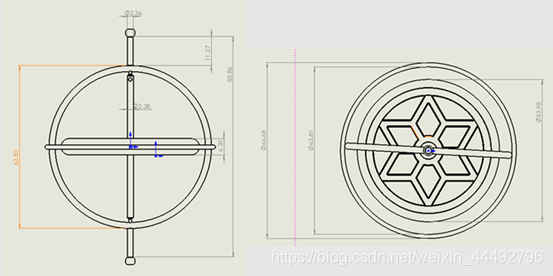
Table 1.1. Parameter of gyroscope
| Geometry | Value |
|---|---|
| Mass of rotor | mr=45g |
| Mass of frame | mf=24g |
| Thickness of rotor | h=6.3mm |
| Height of frame | H=86mm |
| Radius of rotor | Ri=54/2mm |
| Radius of frame torus | Ro=64/2mm |
| Internal diameter of rod | ri=1.2mm |
Predict the direction of precession
According to figure 1.2, the precession of the gyroscope can be predicted by the rotation of the rotor. If the rotor rotates anti-clockwise viewed on the top, the precession trail will be also anti-clockwise from the top view. (Left picture of 1.2) If the rotor rotates clockwise, the precession trail will be clockwise as well.
Figure 1.2. Precession of gyroscope
Section 2: Modelling
Assign coordinate system
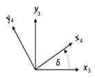
The gyro frame is attached to the ground frame {0} at point O with a ball joint, and the rotor is aligned along OC with a revolute joint. This configuration gives the system 4 degrees of freedom. The gyro frame has 3 from the boll joint and the rotor has 1 from the revolute joint. Frame {1}, {2} describe the tilting of OC, and frame {3},{4} describes the rotation of the gyro frame and the rotor respectively along the OC axis. The resulting coordinate system can be seen in the diagram below:
Find rotation matrix
From the diagram above, one can write the rotation matrix between each frame:
Find angular velocity
The relative angular velocity is:
with the equations above, one can express the absolute angular velocity of each frame:
Find inertia tensor
Rotor
The rotor can be consider as a pie, which can be modelled as a cylinder. The pie has radius Ri, height h and mass m_r. The pole has radius r, height H and mass m_r1. The overlapping volume is taken away from the pole. The inertia tensor about point G in frame {4} is given by
Gyro frame
The frame consists of three parts. Part a is modeled as a cylinder rod of radius r_i along the OC axis. This gives the inertia tenser of the pole around point G in frame {3}:
Part b and c are modeled as a torus of minor radius r_i, major radius r_o and mass m_a, m_b. the axis of part a is colinear to OC and the axis of part b is colinear to the y axis of frame {3}. Their inertia tensor in {3} around G are: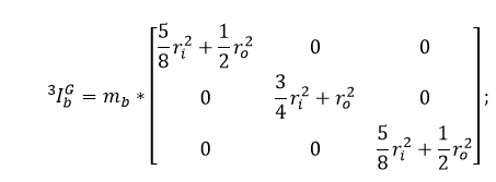
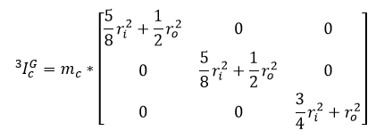
The total combined inertia tenser of the frame in {3} around G is:
Use parallel axis theorem to find the inertia tensor around point O:
Free body diagram
Rotor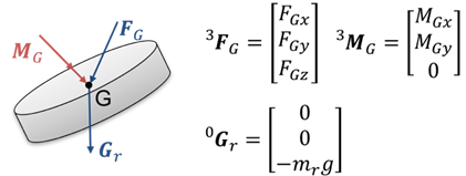
Frame
Newton-Euler equation
The linear Newton-Euler Equation of the rotor is given by:
The angular Newton-Euler Equation of the rotor is given by:
The linear Newton-Euler equation of the gyro frame is given by:
The angular Newton-Euler equation of the gyro frame is given by:
Decouple EOM
The four Newton-Euler 3x3 matrix equations expands to 12 equations. By eliminating internal forces: F_GX F_GY F_GZ, internal moments: M_GX, M_GY, and external forces at O: F_OX, F_OY, F_OZ, we are left with 4 equations of motion corresponds to the 4 degrees of freedom the system has. The 4 equations have the form:
Using the MATLAB equationToMatrix function, we get
By multiplying both side by the inverse of A, the equations are decoupled into the from
Define the state vector X as follows and find its time derivative:
This system of 8 first order ODE can be solved numerically using MATLAB ode45 solver. The solution struct can then be used in the animation.
Section 3. Parameter and Initial Conditions
Geometry parameters
In the process of simulation, the model needs to be simplified appropriately. In this experiment, the gyroscope was simplified into two parts. The first part is the rotor and the second part is the frame. In the process of simulation, the rotor can be considered as a cylinder with uniform mass distribution. Its
radius is Ri =27mm and its height is h=6.3mm. The frame can be seen as consisting of a cylinder and two torus. The internal radius of the cylinder is ri =1.2mm. The external radius of the torus is Ro = 32 mm. And all the data are measured in class.
Mass and inertia
The total mass of the gyroscope is 69g. Assuming that the density of the object is uniform and the mass distribution is uniform, the mass ratio of rotor to frame is 1.85:1. So the mass of rotor is 45 g and that of frame is 24 g.
Inertia is needed in Newton’s Euler formula. Inertia of the gyroscope are calculated in section 2. Notice that: Rotor can be considered as a simple cylinder, but frame consists of three parts, each part needs to calculate inertia separately, then aggregate it into an inertia, and then convert inertia into the value of
coordinate points according to the parallel axis theorem. During the calculation the mass of each part are gotten based on volume of each part.
Initial conditions
Initial condition is one of the necessary conditions for numerical solution. In gyro motion simulation, there are eight initial conditions. The initial conditions are [a0, b0, c0, d0, a-dot0, b-dot0, c-dot0, d-dot0]. The initial conditions can be obtained by observing and estimating gyroscope rotation in video recording.
By analyzing the meaning of each part, we know that a0, c0 and d0 will not significantly affect the gyro’s motion, so we can assign any non-zero values.
b0 determines the angle between the gyro and the numerical direction at the initial position. After comparing with the video, we think that the initial B0 is between 0.1 and 0.2.
b0_dot is obviously zero at the initial position because the gyroscope does not fall immediately or tends to fall.
a0_dot and c0_dot simultaneously affect the rotation of the gyro frame. After repeated color measurement, 25 and-24 rad/s are the closest combination to the video.
d0_dot is the rotational speed of the gyro rotor, which is a very large value. We take clockwise rotation as an example. After repeated comparisons, the d0_dot of video recording belongs to 250-300 rad/s.
To sum up, taking clockwise rotation as an example, the optimum initial conditions of the model are [2pi, 0.1, 2pi, 2pi, 25, 0, -24, 300].
Section 4. Concluding Analysis.
Comparing results with actual motion
Figure 4.1. Comparing between simulation and actual motion.
The figures above represent the images of the motion of the gyroscope recorded in the lab and the MATLAB simulation of the motion of the gyroscope. Comparing both side by side pictorially, we can see that they look similar. A combined video of the simulation and the actual motion of the gyroscope has been for further analysis of the nature of errors which will be discussed below.
Error analysis
The time step used in the analysis is big which may cause inconsistencies between the actual motion and the simulated motion of the gyroscope.
There may be inaccuracy in the simulation due to numerical errors in rounding off answers.
Assuming that there are no frictional forces in the analysis of the motion for the sake of simplifying the problem, though, this is not the actual case. This could be accounted by the fact that the gyroscope does not rotate about a single point. Hence, this can explain the increasing delay between the actual and the simulated motion of the gyroscope.
Assuming no slippage in our analysis for the sake of abstraction, which is not possible in the real case scenario.
Assuming uniform density for the frame of the gyroscope for the ease of abstraction of problem, which is not possible in the real world as anomalies such as impurities in the manufacturing process. Hence, the assumption of the position of the centre of mass, G, could be wrong as well.
Assuming that the gyroscope has been calibrated perfectly and hence we are able to consider a cylinder with 2 tori. However, it is not possible for the actual gyroscope to be perfectly aligned due to impurities present in the whole frame and structure of the rotor.
The errors outlined above can be minimised by taking a smaller time step in our analysis, making more accurate measurements of the model, and taking account of frictional forces in our MATLAB simulation to better match the actual motion of the gyroscope.
Appendix
MATLAB code for calculating Inertia
% Inertia tensor of rotor
I_rotor=(mr/12)*[ 3*Ri^2+h^2 0 0;0 3*Ri^2+h^2 0;0 0 6*Ri^2];
%Inertia tensor of frame
I_a=(ma/12)*[ 3*ri^2+H^2 0 0; 0 3*ri^2+H^2 0;0 0 6*ri^2];
I_b=mb*[5/8*ri^2+1/2*Ro^2 0 0;  0 3/4*ri^2+Ro^2 0; 0  0 5/8*ri^2+1/2*Ro^2];
I_c=mc*[5/8*ri^2+1/2*Ro^2  0 0; 0 5/8*ri^2+1/2*Ro^2 0; 0 0 3/4*ri^2+Ro^2];
I_frame_G=I_a+I_b+I_c;
I_frame_O=I_frame_G+mf*[L^2 0 0; 0 L^2 0; 0 0 0];
MATLAB code for calculating Newton-Euler equation
%Newton Euler Equation of the 'ROTOR'

r_OG_3_dot = cross(w30_3,r_OG_3);

P_rotor = mr * r_OG_3_dot;

P_rotor_dot = diff(P_rotor,t) + cross(w30_3,P_rotor);

FG_3 = P_rotor_dot - R32 * R21 * R10 * [0;0;-mr*g];

h_G_3 = I_rotor * w40_3;

MG_3 = diff(h_G_3,t) + cross(w30_3,h_G_3);

FGx = [1,0,0] * FG_3;

FGy = [0,1,0] * FG_3;

FGz = [0,0,1] * FG_3;

MGx = [1,0,0] * MG_3;

MGy = [0,1,0] * MG_3;

MGz = [0,0,1] * MG_3;

%Newton Euler Equation of the 'FRAME'

P_frame = mf * r_OG_3_dot;

P_frame_dot = diff(P_frame,t) + cross(w30_3,P_frame);

FO_3 = P_frame_dot -
R32 * R21 * R10 * [0;0;-mf * g] + FG_3;

h_frame = I_frame_O * w30_3;

h_frame_dot = diff(h_frame,t) + cross(w30_3,h_frame);

Gf_3=R32*R21*R10*[0;0;-mf*g];

MO_3 = h_frame_dot +
MG_3-cross(r_OG_3,Gf_3)+cross(r_OG_3,FG_3);

FO_3=simplify(FO_3);

MO_3=simplify(MO_3);

FOx = [1,0,0]*FO_3;

FOy = [0,1,0]*FO_3;

FOz = [0,0,1]*FO_3;

MOx= [1,0,0] * MO_3;

MOy= [0,1,0] * MO_3;

MOz= [0,0,1] * MO_3;
MATLAB code for decoupling EoM
%Equation of Motion

eom1=0==MGz;

eom2=0==MOx;

eom3=0==MOy;

eom4=0==MOz;

eoms=[eom1;eom2;eom3;eom4];

%Decoupling the EoM

syms x1 x2 x3 x4 x5 x6 x7 x8 x9 x10 x11 x12

eoms=subs(eoms,{a,b,c,d,diff(a,t),diff(b,t),diff(c,t),diff(d,t),diff(a,t,t),diff(b,t,t),diff(c,t,t),diff(d,t,t)},...  {'x1','x2','x3','x4','x5','x6','x7','x8','x9','x10','x11','x12'});

[A,B] = equationsToMatrix(eoms,[x9,x10,x11,x12]);

SS= inv(A)*B;

disp('Copy this to the function "state_space_equation"');

disp(SS);

%ODE solver of state space equation.

[T,Y]=ode45(@state_space_equation,[0,10],[3*pi/4;0.5; 0; 0; 2;0.1;0.1;-250]);

plot(T,Y);

legend('a','b','c','d','a dot','b dot','c dot','d dot');
%%
MATLAB function for transfer EoM to state-space form
function X_dot=state_space_equation(t,X)

x1=X(1);

x2=X(2);

x3=X(3);

x4=X(4);

x5=X(5);

x6=X(6);

x7=X(7);

x8=X(8);

a_dot=x5;

b_dot=x6;

r_dot=x7;

d_dot=x8;

a_double_dot=
(17288414726746786620460366697579889573437500*x6*x7 +
11149310861738480936570706314367493505468750*x6*x8 +
581259503501260085222115179643902361600000000*cos(x3)*sin(x2)*sin(x3) -
185142646609399561069973562090503698600659326*x5*x6*cos(x2) +
5439412594514319249798385935372254323437500*x6*x7*cos(x3)^2 -
327562034097100628760750829701538085937500*x6*x8*cos(x3)^2 +
5439412594514319249798385935372254323437500*x5*x6*cos(x2)*cos(x3)^2 +
5439412594514319249798385935372254323437500*x5*x7*cos(x3)*sin(x2)*sin(x3) -
327562034097100628760750829701538085937500*x5*x8*cos(x3)*sin(x2)*sin(x3) +
5439412594514319249798385935372254323437500*x5^2*cos(x2)*cos(x3)*sin(x2)*sin(x3))/(101215530668073173845216964394041794087048413*sin(x2));


b_double_dot=
(1118574820063104397737984*sin(x2))/5895738848596540478561 +
(13715573055970318310683*x5^2*sin(2*x2))/35374433091579242871366 +
(21528129759305929082300562209033420800000000*cos(x3)^2*sin(x2))/3748723358076784216489517199779325706927719
- (3971643489819303125000*x5*x7*sin(x2))/17687216545789621435683 -
(1891079497931380468750*x5*x8*sin(x2))/17687216545789621435683 -
(2719706297257159624899192967686127161718750*x6*x7*sin(2*x3))/101215530668073173845216964394041794087048413
+ (163781017048550314380375414850769042968750*x6*x8*sin(2*x3))/101215530668073173845216964394041794087048413
+
(5439412594514319249798385935372254323437500*x5^2*cos(x2)*cos(x3)^2*sin(x2))/101215530668073173845216964394041794087048413
+
(5439412594514319249798385935372254323437500*x5*x7*cos(x3)^2*sin(x2))/101215530668073173845216964394041794087048413
- (327562034097100628760750829701538085937500*x5*x8*cos(x3)^2*sin(x2))/101215530668073173845216964394041794087048413
-
(5439412594514319249798385935372254323437500*x5*x6*cos(x2)*cos(x3)*sin(x3))/101215530668073173845216964394041794087048413;


r1_double_dot=(269549297315610600575987575411949523339352203572203332599433*x5*x6
- 34541888732085906610190968591014827387688240305420684375000*x6*x7*cos(x2) -
22276088427575355430649246400409439140076968217680529687500*x6*x8*cos(x2) +
100361813669704214143202121565715824904471084633265442002211*x5*x6*cos(x2)^2 -
134645594913820479822594485255218871047192878633517206222222*x5*x6*cos(x3)^2 -
10867831873384015392703764922894081866493220803332184375000*x6*x7*cos(x2)*cos(x3)^2
+ 654462049497981035665807182431578414025753480224609375000*x6*x8*cos(x2)*cos(x3)^2
+
123777763040436464429890720332324789180699657830185021847222*x5*x6*cos(x2)^2*cos(x3)^2
-
67322797456910239911297242627609435523596439316758603111111*x5^2*cos(x3)*sin(x2)*sin(x3)
+ 67322797456910239911297242627609435523596439316758603111111*x6^2*cos(x3)*sin(x2)*sin(x3)
-
1161344253463898999300697715664315658808060082021990400000000*cos(x2)*cos(x3)*sin(x2)*sin(x3)
+
56454965583526224518593477704715353657103218513426418736111*x5^2*cos(x2)^2*cos(x3)*sin(x2)*sin(x3)
- 10867831873384015392703764922894081866493220803332184375000*x5*x7*cos(x2)*cos(x3)*sin(x2)*sin(x3)
+
654462049497981035665807182431578414025753480224609375000*x5*x8*cos(x2)*cos(x3)*sin(x2)*sin(x3))/(202226499858700360664690332784340087815755764255444729488322*sin(x2));

d1_double_dot=
(665142957928947*x5^2*cos(x3)*sin(x2)^2*sin(x3))/1997978951687594 -
(665142957928947*x6^2*cos(x3)*sin(x3))/1997978951687594 +
(665142957928947*x5*x6*cos(x3)^2*sin(x2))/1997978951687594 -
(665142957928947*x5*x6*sin(x2)*sin(x3)^2)/1997978951687594;

X_dot=[a_dot; b_dot;
r_dot;d_dot;a_double_dot;b_double_dot;r1_double_dot;d1_double_dot];

end
MATLAB code for animating the numerical solution
clc

clear all

%%

%Set
initial conditions, time span.

Tspan =[0,5];

Initial_con=[0;0.01;1;0;0;0;1;300];

%%

%Get the numerical result. (ODE45)

Sol =ode45(@state_space_equation,Tspan,Initial_con);

dt=0.01;

fps = 1/dt;

t =Tspan(1):0.01:Tspan(2);

X =deval(Sol,t);

%%
%relativeparameters

mr=45*10^-3;


Ri=54/2*10^-3;

Ro=64/2*10^-3;

h=6.3*10^-3;

ma=6.4*10^-3;

mb=8.8*10^-3;

mc=8.8*10^-3;

mf=ma+mb+mc;

ri=1.2*10^-3;

H=86*10^-3;

L=H/2;

g=9.81;

%%

%Create the objects, including rotor, tours A, tours B, rod.

[x_rotor,y_rotor,z_rotor]=cylinder(Ri,50);

z_rotor=z_rotor*h+L-h/2;

[x_rod,y_rod,z_rod]=cylinder(ri,50);

z_rod=z_rod*H;

Circle1_point= linspace(0,2*pi,50);

Circle2_point= linspace(0,Ri,50);

[Top,Bottom]= meshgrid(Circle1_point,Circle2_point);

[Xt,Yt,Z0] =pol2cart(Top,Bottom,Bottom.*0);

Ztop = Z0 +L + h/2;

Zbottom = Z0+ L - h/2;

Xr = Xt;

Yr = Yt;%Rotor and rod


[u,v] =meshgrid(0:7.5:360);

x_torusA=(Ro+ ri * cosd(v)).*cosd(u);

y_torusA=(Ro+ ri * cosd(v)).*sind(u);

z_torusA=ri* sind(v)+L;

%torus A

x_torusB=(Ro+ ri * cosd(v)).*cosd(u);

y_torusB=ri* sind(v);%torus B

z_torusB=(Ro+ ri * cosd(v)).*sind(u)+L;

%%

Motion_test1= VideoWriter('motion_clockwise','MPEG-4');

Motion_test1.FrameRate= fps;

open(Motion_test1);

  %%

    handle = figure;

    hold on;

    for i = 1:length(t)

        cla

        a = X(1,i);

        b = X(2,i);

        c = X(3,i);

        d= X(4,i);

        R23=[cos(c) sin(c) 0;-sin(c) cos(c) 0;0 0 1];

        R32=transpose(R23);

        R12=[1 0 0;0 cos(b) sin(b);0 -sin(b) cos(b)];

        R21=transpose(R12);

        R01=[cos(a) sin(a) 0;-sin(a) cos(a) 0;0 0 1];

        R10=transpose(R01);

        R34=[cos(d) sin(d) 0;-sin(d) cos(d) 0;0 0 1];

        R43=transpose(R34);

        R03 = R01*R21*R23;

        R04 = R03*R34;


[Xrod_rotated,Yrod_rotated,Zrod_rotated] =Objects_Rotate_R03(R03,x_rod,y_rod,z_rod);

        [XA_rotated,YA_rotated,ZA_rotated] =Objects_Rotate_R03(R03,x_torusA,y_torusA,z_torusA);

        [XB_rotated,YB_rotated,ZB_rotated] =Objects_Rotate_R03(R03,x_torusB,y_torusB,z_torusB);

        [Xr_rotated,Yr_rotated,Zr_rotated] =Objects_Rotate_R04(R04,x_rotor,y_rotor,z_rotor);

        [Xt_rotated,Yt_rotated,Zt_rotated] =Objects_Rotate_R04(R04,Xt,Yt,Ztop);

        [Xb_rotated,Yb_rotated,Zb_rotated] =Objects_Rotate_R04(R04,Xr,Yr,Zbottom);


surf(Xrod_rotated,Yrod_rotated,Zrod_rotated,x_rod);

 surf(XA_rotated,YA_rotated,ZA_rotated,x_torusA);

surf(XB_rotated,YB_rotated,ZB_rotated,x_torusB);

surf(Xr_rotated,Yr_rotated,Zr_rotated,x_rotor);

surf(Xt_rotated,Yt_rotated,Zt_rotated,Xt);

surf(Xb_rotated,Yb_rotated,Zb_rotated,Xr);

        colormap hot

        axis on

        axis square

        axis([-H/2 H/2 -H/2 H/2 0 H]);

        view(3);

        writeVideo(Motion_test1,getframe);

    end

         close(Motion_test1);
MATLAB function for rotating the object
function [Xo,Yo,Zo]=Objects_Rotate_R03(R03,Xi,Yi,Zi)

    Xo=zeros(size(Xi,1),size(Xi,2));

    Yo=zeros(size(Xi,1),size(Xi,2));

    Zo=zeros(size(Xi,1),size(Xi,2));

    for i=1:size(Xi,1)

        for j=1:size(Xi,2)

            Output = [Xi(i,j);Yi(i,j);Zi(i,j)];

            Output = R03 * Output;

                Xo(i,j) = Output(1);

                Yo(i,j) = Output(2);

                Zo(i,j) = Output(3);

        end

    end

end

%%

function [Xo,Yo,Zo]=Objects_Rotate_R04(R04,Xi,Yi,Zi)

    Xo=zeros(size(Xi,1),size(Xi,2));

    Yo=zeros(size(Xi,1),size(Xi,2));

    Zo=zeros(size(Xi,1),size(Xi,2));

    for i=1:size(Xi,1)

        for j=1:size(Xi,2)

            Output = [Xi(i,j);Yi(i,j);Zi(i,j)];

            Output = R04 * Output;

                Xo(i,j) = Output(1);
来源:CSDN
作者:X工
链接:https://blog.csdn.net/weixin_44492796/article/details/103584492