http://jamie-wong.com/2016/07/15/ray-marching-signed-distance-functions/
Signed Distance Functions
Signed Distance Functions, or SDFs for short, when passed the coordinates of a point in space, return the shortest disance between that point and some surface. the sign of the return value indicates whether point is inside that surface or outside (hence signed distance function). let us look at an example.
consider a sphere centered at the origin. Points inside the sphere will have a distance from the origin less than the radius, points on the sphere will have distance equal to the radius, and points outside the sphere will have distances greater than the radius.
So our first SDF, for a sphere centered at the origin with radius 1, looks like this:
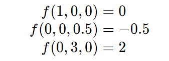
Let’s try some points:
Great, (1, 0, 0) (1,0,0) is on the surface, (0, 0, 0.5) (0,0,0.5) is inside the surface, with the closest point on the surface 0.5 units away, and (0, 3, 0) (0,3,0) is outside the surface with the closest point on the surface 2 units away.
when we working in GLSL shader code, formulas like this will be vectorized. Using the Euclidean norm, the above SDF looks like this:
Which, in GLSL, translates to this:
float sphereSDF(vec3 p)
{
    return length(p) - 1.0;
}
For a bunch of other handy SDFs, check out Modeling with Distance Functions.
http://iquilezles.org/www/articles/distfunctions/distfunctions.htm
The Raymarching Algorithm
once we have something modeled as an SDF, how do we render it? this is where the ray marching algorithm comes in!
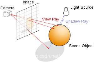
just as in raytracing, we select a position for the camera, put a grid in front of it, send rays from the camera though each point in the grid, with each grid point corresponding to a pixel in the output image.

From “Ray tracing” on Wikipedia
the difference comes in how the scene is defined, which in turn changes our options for finding the intersection between the view ray and the scene.
in raytacing, the scene is typically defined in terms of explicit geometry: triangles, spheres, etc. to find the intersection between the view ray and the scene, we do a series of geometric inersection tests: where does this ray intersect with this triangle, if at all? what about this one? what about this sphere?
Aside: For a tutorial on ray tracing, check out scratchapixel.com. If you’ve never seen ray tracing before, the rest of this article might be a bit tricky.
https://www.scratchapixel.com/lessons/3d-basic-rendering/introduction-to-ray-tracing/how-does-it-work?url=3d-basic-rendering/introduction-to-ray-tracing/how-does-it-work
in raymarching, the entire scene is defined in terms of a signed distance function. to find the intersection between the view ray and the scene, we start at the camera, and move a point along the view ray, bit by bit. at each step, we ask “is this point inside the scene surface?”, or alternately phrased, “Does the SDF evaluate to a negative number at this point?“. If it does, we’re done! We hit something. If it’s not, we keep going up to some maximum number of steps along the ray.
we could just step along a very small increment of the view ray every time, but we can do much better than this (both in terms of speed and in terms of accuracy) using “sphere tracing”, instead of taking a tiny step, we take the maximum step we know is safe without going though the surface: we step by the distance to the surface, which the SDF provides us!
From GPU Gems 2: Chapter 8.
in this diagram, p0 is the camera. the blue line lies along the ray direction cast from the camera through the view plane. the first step taken is quite large: it steps by the shortest distance to the surface. since the point on the surface closest to p0 does not lie along the view ray, we keep stepping until we eventually get to the surface, at p4.
implemented in glsl, this ray marching algorithm looks like this:
float depth = start;
for (int i = 0; i < MAX_MARCHING_STEPS; i++) {
    float dist = sceneSDF(eye + depth * viewRayDirection);
    if (dist < EPSILON) {
        // We're inside the scene surface!
        return depth;
    }
    // Move along the view ray
    depth += dist;

    if (depth >= end) {
        // Gone too far; give up
        return end;
    }
}
return end;
combining that with a bit of code to select the view ray direction appropriately, the sphere SDF, and making any part of the surface that gets hit red, we end up with this:
Voila, we have a sphere! (Trust me, it’s a sphere, it just has no shading yet.)
surface normals and lighting
most lighting models in computer graphics use some concept of surface normals to calcualte what color a material should be at a given point on the surfae. when surfaces are defined by explictly geometry, like polygons, the normals are usually specified for each vertex, and the normal at any given point on a face can be found by interpolating the surrouding vertex normals.
so how do we find surface normals for a scene defined by a signed distance function? we take the gradient! conceptually, the gradient of a function f at point (x,y,z) tells u what direction to move in from (x,y,z) to most rapidly increase the vaue of f. this will be our surface normal.
here’s the intuition: for a point
on the surface, f (our SDF), evaluates to zero.
on the inside of that surface, f goes negative, and
on the outside, it goes positive.
so the direction at the surface which will bring u from negative to positive most rapidly will be orthogonal to the surface.
But no need to break out the calculus chops here. Instead of taking the real derivative of the function, we’ll do an approximation by sampling points around the point on the surface, much like how you learned to calculate slope in a function as over rise-over-run before you learned how to do derivatives.

/**
 * Using the gradient of the SDF, estimate the normal on the surface at point p.
 */
vec3 estimateNormal(vec3 p) {
    return normalize(vec3(
        sceneSDF(vec3(p.x + EPSILON, p.y, p.z)) - sceneSDF(vec3(p.x - EPSILON, p.y, p.z)),
        sceneSDF(vec3(p.x, p.y + EPSILON, p.z)) - sceneSDF(vec3(p.x, p.y - EPSILON, p.z)),
        sceneSDF(vec3(p.x, p.y, p.z  + EPSILON)) - sceneSDF(vec3(p.x, p.y, p.z - EPSILON))
    ));
}
Armed with this knowledge, we can calculate the normal at any point on the surface, and use that to apply lighting with the Phong reflection model from two lights, and we get this:
By default, all of the animated shaders in this post are paused to prevent it from making your computer sound like a jet taking off. Hover over the shader and hit play to see any animated effects.
Constructive Solid Geometry
Constructive Solid Geometry, or CSG for short, is a method of creating complex geometric shapes from simple ones via boolean operations. this diagram from WikiPedia shows what’s possible with the technique:
From “Constructive solid geometry” on Wikipedia
CSG is built on 3 primitive operations: intersection ( \cap ∩ ), union ( \cup ∪ ), and difference ( − ).
it turns out these operations are all concisely expressible when combining two surface expressed as SDFs.
float intersectSDF(float distA, float distB) {
    return max(distA, distB);
}

float unionSDF(float distA, float distB) {
    return min(distA, distB);
}

float differenceSDF(float distA, float distB) {
    return max(distA, -distB);
}
If you set up a scene like this:
float sceneSDF(vec3 samplePoint) {
    float sphereDist = sphereSDF(samplePoint / 1.2) * 1.2;
    float cubeDist = cubeSDF(samplePoint) * 1.2;
    return intersectSDF(cubeDist, sphereDist);
}
Then you get something like this (see section below about scaling to see where the division and multiplication by 1.2 comes from).
In this same Shadertoy, you can play around with the union and difference operations too if you edit the code.
It’s interesting to consider the SDF produced by these binary operations to try to build an intuition for why they work.
putting it all together
with the primitives in this post, u can now create some pretty interesting, complex scenes. combining those with a simple trick of using the normal vector as the ambient/diffuse component of the material, and u can create something like the shader at the start of the post. here it is again.
来源:CSDN
作者:wodownload2
链接:https://blog.csdn.net/wodownload2/article/details/103864269