问题
I have a 2D shape stored as a path element in an SVG. The shapes consist of Bezier curves and line segments.
I also have a set of equally space points along the shape that I am generating using arc length parameterization.
How can I use either the SVG or these points to determine the medial axis of the shape?
I am using Python, but any sort of pseudocode or algorithm advice would be much appreciated.
The following is an example of the types of shapes I am dealing with, and the red dots are my sampled points along the curve.

回答1:
A tad late but here goes:
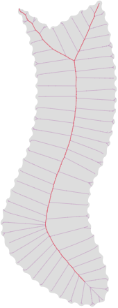
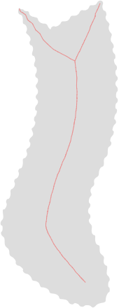
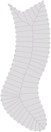
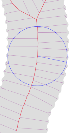
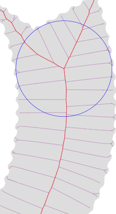
The pictures above shows: (I've converted the OP's image to SVG with an online tool hence the ragged boundary that is an artifact of the red dots) 1. Superimposed Medial and Scale Axis Transform (MAT and SAT). 2. Scale Axis Transform only. 3. Medial Axis Transform only. 4. One of many 2-prongs (see below). 5. The single 3-prong in the SAT (there are many in the MAT).
To find the Medial Axis (MA) or Medial Axis Transform (MAT) (purple curves in above image) the following algorithm can be used (based on a paper by Choi, Choi, Moon and Wee - see a demo implementation here that also handles intersecting shapes and shapes with holes). Other algorithms also exist.
The algorithm is much harder to implement than finding a binary image (e.g. bitmap) skeleton (a.k.a. grassfire or discrete transform) but has several advantages (such as being analytic). To simplify things, the discussion below only handles the case of simple (non-intersecting) shapes without holes.
Some definitions
- Curve - A parametric bezier curve with parameter t ∈ [0,1]. In other words, a typical curve as used in vector graphics.
- Shape (Ω) - (Definition taken directly from the paper) - "the closure of a connected bounded open subset in ℝ² bounded by a finite number of mutually disjoint simple closed curves." For the purposes of this answer it can be further assumed that the shape has no holes. In simple terms it is the area enclosed by the boundary given by a number of curves - the filled gray part in the image above.
- Boundary - The boundary of the shape. In other words, an indexed sequence of curves such that the starting point of any curve at t=0 corresponds to the previous curve's endpoint at t=1. The boundary is assumed positively oriented (i.e. by walking along the boundary in an anti-clockwise direction the shape will always be to your left).
- Boundary point - Any point on the shape boundary fully identified by an index identifying the curve and a t curve paramter.
- Maximal disk - Disks within the shape not occluded by any other disk also within the shape. Every maximal disk can be identified by 1 or more (usually 2) boundary points and its center point.
- n-prong - A maximal disk touching the shape boundary tangentially at n points.
- Branch point - An n-prong maximal disk center with n >= 3. In other words a point on the MA that forms a vertex in the MA planar tree.
- Medial Axis (MA) - The union of the centers of all n-prongs.
- Medial Axis Transform (MAT) - The union of all n-prongs. In other words, the radius of the maximal disks are included in the definition.
- Contact point (cp) - A boundary point linked to a unique maximal disk that has already been found.
- Sharp corner - A boundary point, usually at curve parameter t = 0 or t = 1, that is not differentiable (not smooth) and that forms an interior angle < 180°.
- Dull corner - Same as a sharp corner except the angle > 180°.
- Cp graph - A graph (not necessarily planar) with vertices being
contact points thus also containing information regarding all found
maximal disks and in turn the entire MAT. Each vertex (cp) in the graph
has the following edges:
- next - The first contact point found from the current one by walking anti-clockwise around the boundary.
- prev - The first contact point found from the current one by walking clockwise around the boundary.
- next-around - The first contact point found by going around the maximal disk in an anti-clockwise direction.
- prev-around - The first contact point found by going around the maximal disk in a clockwise direction. We can view each of the above as an operator (.) on a contact point returning another contact point by following an edge, e.g. if a is a contact point, then a.next is another contact point.
Some notes
- The Medial Axis Transform forms an unrooted planar tree with tree leaves at every 1-prong center (including sharp corners); if the shape has holes then the MAT is a planar graph.
- You can remove noise on the shape boundary by applying a Scale Axis Transform (SAT) (red curves in above image) to the MAT. The demo implements such a transform, based on this research. However, the demo improves the algorithm by ensuring the SAT is a subset of the MAT and guarantees topology preservation.
Algorithm overview
- Find all 1-prongs; they are exactly the Medial Axis tree leaves. These are the sharp corners and the 1-prongs touching a boundary point with maximum local inward curvature. Add the contact points of the 1-prongs to the cp-graph. Note that since 1-prongs have one contact point only, the edges next-around and prev-around will just return the found contact point again.
- For a representative set of boundary points (such as those red dots given by the OP), calculate their maximal disks. They will generally be 2-prongs. (See 'finding a 2-prong' below). Add their contact points to the cp-graph by connecting the appropriate edges. Note that in this case, since we found 2-prongs, if next-around (or prev-around) is followed twice one will be back at the same contact point.
Finally find the n-prongs for n >= 3. Starting from each contact point:
- traverse the cp-graph by starting with a contact point (say cp1) and applying cp1.next.next-around repeatedly until you are back at cp1.
If either 1 or 2 iterations of the above occured move to the next contact point on the boundary (using next). If, however, 3 or more iterations were required, it can be proved that a 3-prong branch point exists and should be inserted with contact points on each boundary piece between cp1 and cp1.next.
In that case, insert the 3-prong (see below on how to find these) and go back to step 1, again starting from cp1.
- Repeat step 1 and 2 until all 3-prongs have been found.
- The structure of the MAT has now been found implicitly. To extract the MAT one needs to traverse the cp-graph. Choose any contact point (call it cp1) as the root (for simplicity let's assume it to be linked to a 2-prong), and apply next (call it cp2). A line can now be drawn from cp1's linked maximal disk center to that of cp2. This line is an approximation of a subset of the MA. A much better approximation is obtained via interpolation between the points since we know the boundary tangents at the contact points. Let the two line endpoints be the endpoints of a quadratic bezier curve. Since the orientation of the MA at the two maximal disk centers are known exactly (via the average of the 2 boundary tangents) we have the derivatives of the quadratic beziers at the endpoints too and we can construct a best approximation qudratic bezier curve between the points. If cp2 is linked to a 3-prong it implies that the planar tree formed by the MA bifurcates (i.e. branches ot forks) and we need to follow both MA edges (by using, for example, a stack or recursion). If, on the other hand, cp2 is linked to a 1-prong a leaf of the MA has been reached and the traversal stops for that edge. In fact, since the MA forms a planar tree the traversal algorithm is essentialy the same as that of any other tree data structure.
Finding a 2-prong
I will summarize here but the paper by Choi et al. explains this part quite clearly and is easy to follow.
Choose a point on the boundary that will be the first contact point of our 2-prong and call it bp1. Draw an inward normal ray form the boundary point (i.e the first 'prong' of the 2-prong to be found). Now iterate:
- Select a point, p1, (at a distance d1 from bp1 along this ray) with d1 large enough such that a circle (drawn tangentially at bp1 with center on the ray) will cut the boundary in at least one more point.
- Find the closest boundary point to p1, call it bp2. Finally, find the point on the ray equidistant from bp1 and bp2 and call it p2.
- Go back to step 2 with p2 the new p1.
- Repeat steps 2 and 3 until the distance from p1 to the two boundary points are equal to within some tolerance. The 2-prong has now been found with bp1 and bp2 its two contact points and p1 its center.
Finding a 3-prong
Here we deviate a bit from the paper by constructing a circumcircle as opposed to using a potential function.
- Select the boundary point's (cp1's) linked maximal disk center as an initial guess to the 3-prong center to be found. Call it p.
- Find the 3 closest points to p seperately to each of the 3+ boundary pieces.
- Construct the circumcircle of those points and use its center as the new point p.
- Repeat steps 2 and 3 until the distance to the 3 boundary pieces from p is equal to within some tolerance.
- Mark the 3 boundary points thus found as contact points of the 3-prong. The point p is the center of the 3-prong.
Please feel free to ask if anything is unclear.
回答2:
you can see the code from skimage (scikit-image). you will find the code for skeletonization and also for medial-axis (skimage.morphology.medial_axis)
The source are available at this address : https://github.com/scikit-image/scikit-image/blob/v0.12.2/skimage/morphology/_skeletonize.py#L103
This algorithm computes the medial axis transform of an image as the ridges of its distance transform.
The different steps of the algorithm are as follows
A lookup table is used, that assigns 0 or 1 to each configuration of
   the 3x3 binary square, whether the central pixel should be removed
   or kept.

We want a point to be removed if it has more than one neighbor
   and if removing it does not change the number of connected components.


The distance transform to the background is computed, as well as
   the cornerness of the pixel.

The foreground (value of 1) points are ordered by
   the distance transform, then the cornerness.

A cython function is called to reduce the image to its skeleton. It
   processes pixels in the order determined at the previous step, and
   removes or maintains a pixel according to the lookup table.

Because
   of the ordering, it is possible to process all pixels in only one
   pass.
I hope it will help you
来源:https://stackoverflow.com/questions/29921826/how-do-i-calculate-the-medial-axis-for-a-2d-vector-shape