简述:
• 连接管理器 (CM)
Arm® Cortex®-M4 处理器
– 125MHz
– 512KB 的闪存(受 ECC 保护)
– 96KB 的 RAM(受 ECC 保护或奇偶校验保护)
– 高级加密标准 (AES) 加速器
– 通用 CRC (GCRC)
– 32 通道微型直接存储器存取 (µDMA) 控制器
– 通用异步接收器/发送器 (CM-UART)
– 内部集成电路 (CM-I2C)
– 同步串行接口 (SSI)
– 10/100 以太网 1588 MII/RMII
– MCAN (CAN-FD)• CM-C28x 共享通信外设
– EtherCAT®从控制器 (ESC)
– USB 2.0 (MAC + PHY)
– 两个控制器局域网 (CAN) 模块(引脚可引导)
如何开始使用CM
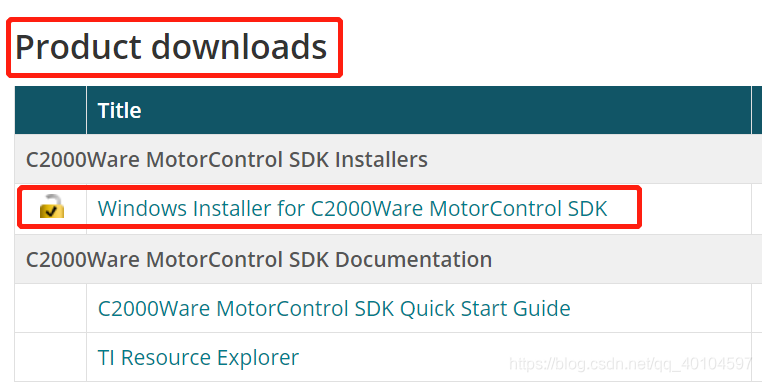
1. 下载并安装C2000WARE-MOTORCONTROL-SDK(这里有CM相关·的例程):
C2000WARE-MOTORCONTROL-SDK下载
之后就是跟着安装向导一步步安装就好了
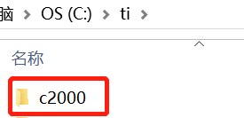
安装完之后在安装路径会有一个文件,如图:
2.找到28388-cm相关的例程,并导入到CCS中
Step1:
Step2:找到下图中所示的项目
Step3:导入项目(我这里已经导过了)
CM-程序接口API资料:
链接:CM相关API和文档
提取码:i416
CM框图:
TMS320F2838x Microcontrollers TRM.pdf 3695页
1. CM-C28X-EnterCAT(ESC)
简述:
Ethernet for Control Automation Technology( EtherCAT) is an Ethernet-based fieldbus system, invented
by Beckhoff Automation™ and is standardized in IEC 61158. All the slave nodes connected to the bus
interpret, process, and modify the data addressed to them in progress, without having to buffer the frame
inside the node.
The frames are directly forwarded with minimum additional delay. This real-time behavior, frame
processing and forwarding requirements are implemented by the EtherCAT slave controller hardware.
EtherCAT does not require software interaction for data transmission inside the slaves. EtherCAT only
defines the MAC layer while the higher layer protocols and stack are implemented in software on the
microcontrollers connected to the ESC.
A list of relevant terms and definitions as shown below.
翻译:用于自动化控制的以太网技术(EnterCat)基于以太网现场总线系统,是德国倍福公司发明的并且符合IEC 61158标准。所有的从节点连接到总线【解释,过程】然后修改发送给他们的数据,而不必在节点中缓冲帧。
这个帧以最小的额外延时被直接发送。这种实时行为,帧被处理和发送请求是通过EnterCAT从硬件控制器执行的。对于内部从机的数据传输EnterCAT不需要软件交互。当更高的协议层和堆栈在微控制器连接到ESC中的软件里被执行时EnterCAT仅定义MAC协议层【太长了太长了不知道翻译的对不对…】。
相关术语和定义的列表如下所示:
ESC(EnterCAT Slave Controller) 特性:
The ESC on this MCU provides the following functionality.
• Up to 2 MII ports to connect to EtherCAT PHYs
最多2个MII端口连接到EtherCAT PHYs
• 64-bit distributed clocking. //64bit分布式时钟
– Sync output signals to synchronize device events and latch input signals supporting time stamping
for events.
同步输出信号同步设备事件和锁存器输入信号支持时间戳
– Distributed clock features of SYNC0/1 (o/ps) and LATCH0/1 able to synchronize GPIOs and allow inputs from any GPIOs as well as other muxing options for internal device events.
分布式时钟SYNC0/1 (o/ps) 和 LATCH0/1的特点是可以同步GPIOs并且允许任何GPIOs以及其他对于内部驱动事件复用器件作为输入
• 8 FMMUs
– Supports all native types of RD/ WR/ RDWR and built-in features of bit/byte addressing
支持所有本地类型的RD/ WR/ RDWR和内置的位/字节寻址功能
• 8 Sync Managers //8个同步管理器
• I2C EEPROM interface
• Up-to 32 general-purpose inputs and 32 General purpose outputs
多达32个通用输入和32个通用输出
• Process data interface through 16-bit asynchronous interface
通过16位异步接口处理数据接口
• 2 SYNC and 2 LATCH signals connected to GPIO pads as well as critical signals internal to the chip
2个同步和2个锁存器信号连接到GPIO板以及芯片内部的关键信号
• 16 KB Process Data RAM with parity
具有奇偶校验的16kb进程数据RAM
来源:CSDN
作者:qq_40104597
链接:https://blog.csdn.net/qq_40104597/article/details/104372210


