文章目录
序言
最近开始了W5500的编程之旅,我从商家给的例程开始学习,但是渐渐地发现,这些例程有一些缺点(功能不够完善,可移植性差,代码编写不规范,接口不够人性化等等),所以我开始使用WIZnet的官方库。官方库写得很好,移植也很简单,功能全面(毕竟自己的产品)。本篇文章我将会对我最近的学习经历进行一下总结,同时安排一下下一阶段的学习任务。我将分为如下几个部分进行介绍:
- W5500芯片简介
- 库文件组成介绍
- 库文件移植过程
- 官方库源码分析
- 总结
W5500芯片简介
W5500 是一款全硬件 TCP/IP 嵌入式以太网控制器,为嵌入式系统提供了更加简易的互联网连接方 案。W5500 集成了 TCP/IP 协议栈,10/100M 以太网数据链路层(MAC) 及物理层(PHY),使得 用户使用单芯片就能够在他们的应用中拓展网络连接。
久经市场考验的 WIZnet 全硬件 TCP/IP 协议栈支持 TCP,UDP,IPv4,ICMP,ARP,IGMP 以及 PPPoE 协议。W5500 内嵌 32K 字节片上缓存以供以太网包处理。如果你使用 W5500, 你只需要一些简单 的 Socket 编程就能实现以太网应用。这将会比其他嵌入式以太网方案 更加快捷、简便。用户可以同 时使用 8 个硬件 Socket 独立通讯。
W5500 提供了 SPI(外设串行接口)从而能够更加容易与外设 MCU 整合。而且, W5500 的使用了新的高效SPI协议支持 80MHz 速率,从而能够更好的实现高速网络通讯。 为了减少系统能耗, W5500 提供了网络唤醒模式(WOL)及掉电模式供客户选择使用。
特点:
- 支持硬件 TCP/IP 协议:TCP, UDP, ICMP, IPv4, ARP, IGMP, PPPoE
- 支持 8 个独立端口(Socket)同时通讯
- 支持掉电模式,支持网络唤醒
- 支持高速串行外设接口(SPI 模式 0,3)
- 内部 32K 字节收发缓存
- 内嵌 10BaseT/100BaseTX 以太网物理层(PHY)
- 支持自动协商(10/100-Based 全双工/半双工)
- 不支持 IP 分片
- 3.3V 工作电压,I/O 信号口 5V 耐压;
- LED 状态显示(全双工/半双工,网络连接,网络速度,活动状态)
- 48 引脚 LQFP 无铅封装(7x7mm, 0.5mm 间距)
适用领域:
- 家庭网络设备: 机顶盒、个人录像机、数码媒体适配器
- 串行转以太网: 门禁控制、LED 显示屏、无线 AP 继电器等
- 并行转以太网: POS/微型打印机、复印机
- USB 转以太网: 存储设备、网络打印机
- GPIO 转以太网: 家庭网络传感器
- 安全系统: 数字录像机、网络摄像机、信息亭
- 工厂和楼宇自动化控制系统
- 医疗监测设备
- 嵌入式服务器
注:是的,没错,上面的就是从数据手册上原模原样CV下来的(手动滑稽)
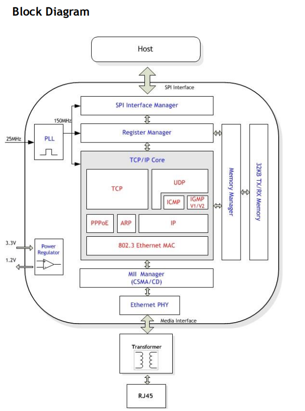
原理方框图:

仔细观察上图,我们看到芯片外围有时钟接口、电源接口,SPI通信接口,以及以太网数据收发接口。芯片内部主要分为SPI接口管理,芯片寄存器管理,收发缓存管理,传输层的各种通信协议,网络层的IP协议,链路层的MAC,连接链路层和物理层的MII接口,以及最后的物理层。详细的信息可以自己去看数据手册,里面有芯片的工作原理介绍,存储空间介绍,各种寄存器功能介绍等等。
注:一定要通读一遍数据手册哦!!!!!!!
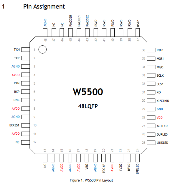
引脚分配图:

库文件组成介绍
ioLibrary Driver
The ioLibrary means “Internet Offload Library” for WIZnet chip. It includes drivers and application protocols.
The driver (ioLibrary) can be used for the application design of WIZnet TCP/IP chips as W5500, W5300, W5200, W5100 W5100S.
ioLibrary
This driver provides the Berkeley Socket type APIs.
- Directory Structure
[外链图片转存失败,源站可能有防盗链机制,建议将图片保存下来直接上传(img-bCnuFNu6-1573113603901)(http://wizwiki.net/wiki/lib/exe/fetch.php?media=products:w5500:iolibrary_bsd.jpg “ioLibrary”)]
- Ethernet : SOCKET APIs like BSD & WIZCHIP(W5500 / W5300 / W5200 / W5100 / W5100S) Driver
- Internet :
- DHCP client
- DNS client
- FTP client
- FTP server
- SNMP agent/trap
- SNTP client
- TFTP client
- HTTP server
- MQTT Client
- Others will be added.
官方库主要就分为以上两个部分:Ethernet,Internet。Internet将作为我下一阶段的学习内容,这次我主要介绍一下Ethernet中的内容
Ethernet目录主要分为三个部分:W5500,socket,wizchip_conf;我在这里先概述一下每个模块的作用,W5500主要负责基本的读写功能,wizchip_conf主要是和移植配置相关的,socket主要负责套接字API的实现。在最后的章节,我们将一起去看看每个文件的作用。
库文件移植过程
先把上面的6个文件放到工程文件夹下面,具体怎么放看个人喜好。
移植主要分为两个步骤:准备接口函数,将这些接口函数与W5500的库绑定
准备接口函数
需要的函数如下
//SPI写入函数
void SPI1WriteByte(uint8_t TxData)
{
    while((SPI1->SR&SPI_I2S_FLAG_TXE)==0);   //等待发送区空
    SPI1->DR=TxData;                                         //发送一个byte
    while((SPI1->SR&SPI_I2S_FLAG_RXNE)==0); //等待接收完一个byte
    SPI1->DR;
}
//SPI读取函数
uint8_t SPI1ReadByte(void)
{
    while((SPI1->SR&SPI_I2S_FLAG_TXE)==0);   //等待发送区空
    SPI1->DR=0xFF;                                               //发送一个空数据产生输入数据的时钟
    while((SPI1->SR&SPI_I2S_FLAG_RXNE)==0); //等待接收完一个byte
    return SPI1->DR;
}
//片选函数
void SPI1_CS_Select(void)
{
    GPIO_ResetBits(GPIOA,GPIO_Pin_4);
}
//片选取消函数
void SPI1_CS_Deselect(void)
{
    GPIO_SetBits(GPIOA,GPIO_Pin_4);
}
//进入临界区函数
void SPI_CrisEnter(void)
{
    __set_PRIMASK(1);
}
//退出临界区函数
void SPI_CrisExit(void)
{
    __set_PRIMASK(0);
}
如果认真地阅读了数据手册,前三个我们都很容易理解。但对于到目前为止一直进行裸机开发的小朋友,临界区这个概念有点陌生,下面我解释一下。
在操作系统上面开发程序,系统会通过任务调度来协调任务的运行,一个程序可能在运行过程中被操作系统剥夺了CPU使用权,大多数情况下这是没问题的,但是有些情况我们不希望程序被中断,也就是我们希望某段代码必须一次执行完,这时候我们就要屏蔽所有中断,禁止任务调度,以此来确保这段程序不被中断。我们就称这段程序是处于临界区的。
上面的六个函数是针对特定芯片的,呈现出来的功能就是:读写SPI,片选(片选取消)某个引脚(根据你的模块接线来确定这个函数与哪个引脚对应),进入(退出)临界区。
接口绑定
我们准备如下函数来将上面的六个函数
void W5500Register(void)
{
	// First of all, Should register SPI callback functions implemented by user for accessing WIZCHIP
    /* Critical section callback */
    reg_wizchip_cris_cbfunc(SPI_CrisEnter, SPI_CrisExit);   //注册临界区函数
    /* Chip selection call back */
#if   _WIZCHIP_IO_MODE_ == _WIZCHIP_IO_MODE_SPI_VDM_
    reg_wizchip_cs_cbfunc(SPI1_CS_Select, SPI1_CS_Deselect);//注册SPI片选信号函数
#elif _WIZCHIP_IO_MODE_ == _WIZCHIP_IO_MODE_SPI_FDM_
    reg_wizchip_cs_cbfunc(SPI_CS_Select, SPI_CS_Deselect);  // CS must be tried with LOW.
#else
   #if (_WIZCHIP_IO_MODE_ & _WIZCHIP_IO_MODE_SIP_) != _WIZCHIP_IO_MODE_SIP_
      #error "Unknown _WIZCHIP_IO_MODE_"
   #else
      reg_wizchip_cs_cbfunc(wizchip_select, wizchip_deselect);
   #endif
#endif
    /* SPI Read & Write callback function */
    reg_wizchip_spi_cbfunc(SPI1ReadByte, SPI1WriteByte);    //注册读写函数

}
上面的三处中文注释就是用来将上一章的六个函数与库进行绑定的,到这里我们的的移植就算结束了,但是我们的探索之旅还没有结束,我们要进去看看这些绑定到底是怎么完成的。
我们来看看reg_wizchip_cris_cbfunc(SPI_CrisEnter, SPI_CrisExit)
void reg_wizchip_cris_cbfunc(void(*cris_en)(void), void(*cris_ex)(void))
{
   if(!cris_en || !cris_ex)
   {
      WIZCHIP.CRIS._enter = wizchip_cris_enter;
      WIZCHIP.CRIS._exit  = wizchip_cris_exit;
   }
   else
   {
      WIZCHIP.CRIS._enter = cris_en;
      WIZCHIP.CRIS._exit  = cris_ex;
   }
}
在这里,我们发现一个if_else分支,第一个是if两个参数中有一个是空的,就执行下面的语句,否则就将这两个参数分别赋值给某个东西,那么赋值给什么呢?我们继续往下看WIZCHIP
_WIZCHIP  WIZCHIP =
      {
      .id                  = _WIZCHIP_ID_,
      .if_mode             = _WIZCHIP_IO_MODE_,
      .CRIS._enter         = wizchip_cris_enter,
      .CRIS._exit          = wizchip_cris_exit,
      .CS._select          = wizchip_cs_select,
      .CS._deselect        = wizchip_cs_deselect,
      .IF.BUS._read_byte   = wizchip_bus_readbyte,
      .IF.BUS._write_byte  = wizchip_bus_writebyte
//    .IF.SPI._read_byte   = wizchip_spi_readbyte,
//    .IF.SPI._write_byte  = wizchip_spi_writebyte
      };
WIZCHIP是一个_WIZCHIP类型的结构体,我们来看看_WIZCHIP是什么样子(我第一次见到用这种方式给结构体赋值(手动大哭))
typedef struct __WIZCHIP
{
   uint16_t  if_mode;               ///< host interface mode
   uint8_t   id[6];                 ///< @b WIZCHIP ID such as @b 5100, @b 5200, @b 5500, and so on.
   /**
    * The set of critical section callback func.
    */
   struct _CRIS
   {
      void (*_enter)  (void);       ///< crtical section enter
      void (*_exit) (void);         ///< critial section exit
   }CRIS;
   /**
    *  The set of @ref\_WIZCHIP_ select control callback func.
    */
   struct _CS
   {
      void (*_select)  (void);      ///< @ref \_WIZCHIP_ selected
      void (*_deselect)(void);      ///< @ref \_WIZCHIP_ deselected
   }CS;
   /**
    * The set of interface IO callback func.
    */
   union _IF
   {
      /**
       * For BUS interface IO
       */
      struct
      {
         uint8_t  (*_read_byte)  (uint32_t AddrSel);
         void     (*_write_byte) (uint32_t AddrSel, uint8_t wb);
      }BUS;
      /**
       * For SPI interface IO
       */
      struct
      {
         uint8_t (*_read_byte)   (void);
         void    (*_write_byte)  (uint8_t wb);
      }SPI;
      // To be added
      //
   }IF;
}_WIZCHIP;
这个结构体里面有两个结构体和一个共同体,第一个结构体里面是两个函数指针分别代表进出临界区,第二个结构体里面的两个指针分别代表片选和取消片选,第三个共同体里面有两个结构体,每个结构体里面都有两个函数指针,分别代表读写字节。我们回到它的上一层
_WIZCHIP  WIZCHIP =
      {
      .id                  = _WIZCHIP_ID_,
      .if_mode             = _WIZCHIP_IO_MODE_,
      .CRIS._enter         = wizchip_cris_enter,
      .CRIS._exit          = wizchip_cris_exit,
      .CS._select          = wizchip_cs_select,
      .CS._deselect        = wizchip_cs_deselect,
      .IF.BUS._read_byte   = wizchip_bus_readbyte,
      .IF.BUS._write_byte  = wizchip_bus_writebyte
//    .IF.SPI._read_byte   = wizchip_spi_readbyte,
//    .IF.SPI._write_byte  = wizchip_spi_writebyte
      };
我们在这里定义了一个_WIZCHIP结构体,我们给它初始化一些值,这些值是一些空函数(如果我们不提供自己的函数,我们就需要再这些函数里面直接实现,但这样做很明显不好)。
再回到上一层
void reg_wizchip_cris_cbfunc(void(*cris_en)(void), void(*cris_ex)(void))
{
   if(!cris_en || !cris_ex)
   {
      WIZCHIP.CRIS._enter = wizchip_cris_enter;
      WIZCHIP.CRIS._exit  = wizchip_cris_exit;
   }
   else
   {
      WIZCHIP.CRIS._enter = cris_en;
      WIZCHIP.CRIS._exit  = cris_ex;
   }
}
我们重新给这些结构体赋予了我们给的函数
看到这里,聪明的小伙伴一定已经知道了,是的没错,W5500官方库的其它部分都会通过这个结构体来调用这些函数。
是不是学到一招,将来自己写通用库函数的时候可以借鉴一下这种绑定方式
官方库源码分析
我们现在进入到了最令人激动人心的时刻,源码分析,我们要去看看官方是怎么去控制芯片的行为的。由于内容太多,我不可能一行一行代码去分析,我打算把分析分为三大部分,然后每个部分挑选一些代码出来看看。
wizchip_conf.c 和wizchip_conf.h
我把所有函数原型贴出来
void 	  wizchip_cris_enter(void);
void 	  wizchip_cris_exit(void);
void 	wizchip_cs_select(void);
void 	wizchip_cs_deselect(void);
uint8_t wizchip_bus_readbyte(uint32_t AddrSel) ;
void 	wizchip_bus_writebyte(uint32_t AddrSel, uint8_t wb);
uint8_t wizchip_spi_readbyte(void) ;
void 	wizchip_spi_writebyte(uint8_t wb);
void reg_wizchip_cris_cbfunc(void(*cris_en)(void), void(*cris_ex)(void));
void reg_wizchip_cs_cbfunc(void(*cs_sel)(void), void(*cs_desel)(void));
void reg_wizchip_bus_cbfunc(uint8_t(*bus_rb)(uint32_t addr), void (*bus_wb)(uint32_t addr, uint8_t wb));
void reg_wizchip_spi_cbfunc(uint8_t (*spi_rb)(void), void (*spi_wb)(uint8_t wb));
//如果上一章节看懂了,上面的函数应该没什么问题
int8_t ctlwizchip(ctlwizchip_type cwtype, void* arg);
int8_t ctlnetwork(ctlnetwork_type cntype, void* arg);
void wizchip_sw_reset(void);
int8_t wizchip_init(uint8_t* txsize, uint8_t* rxsize);
void wizchip_clrinterrupt(intr_kind intr);
intr_kind wizchip_getinterrupt(void);
void wizchip_setinterruptmask(intr_kind intr);
intr_kind wizchip_getinterruptmask(void);
int8_t wizphy_getphylink(void);
int8_t wizphy_getphypmode(void);
void wizphy_reset(void);
void wizphy_setphyconf(wiz_PhyConf* phyconf);
void wizphy_getphyconf(wiz_PhyConf* phyconf);
void wizphy_getphystat(wiz_PhyConf* phyconf);
int8_t wizphy_setphypmode(uint8_t pmode);
void wizchip_setnetinfo(wiz_NetInfo* pnetinfo);
void wizchip_getnetinfo(wiz_NetInfo* pnetinfo);
int8_t wizchip_setnetmode(netmode_type netmode);
netmode_type wizchip_getnetmode(void);
void wizchip_settimeout(wiz_NetTimeout* nettime);
void wizchip_gettimeout(wiz_NetTimeout* nettime);
//至于上面函数的含义,在它的头文件wizchip_conf.h中都有说明
我们来分析两个函数:ctlwizchip和ctlnetwork
ctlwizchip
int8_t ctlwizchip(ctlwizchip_type cwtype, void* arg)
{
   uint8_t tmp = 0;
   uint8_t* ptmp[2] = {0,0};
   switch(cwtype)
   {
      case CW_RESET_WIZCHIP:
         wizchip_sw_reset();
         break;
      case CW_INIT_WIZCHIP:
         if(arg != 0)
         {
            ptmp[0] = (uint8_t*)arg;
            ptmp[1] = ptmp[0] + _WIZCHIP_SOCK_NUM_;
         }
         return wizchip_init(ptmp[0], ptmp[1]);;
      case CW_CLR_INTERRUPT:
         wizchip_clrinterrupt(*((intr_kind*)arg));
         break;
      case CW_GET_INTERRUPT:
        *((intr_kind*)arg) = wizchip_getinterrupt();
         break;
      case CW_SET_INTRMASK:
         wizchip_setinterruptmask(*((intr_kind*)arg));
         break;
      case CW_GET_INTRMASK:
         *((intr_kind*)arg) = wizchip_getinterruptmask();
         break;
   #if _WIZCHIP_ > 5100
      case CW_SET_INTRTIME:
         setINTLEVEL(*(uint16_t*)arg);
         break;
      case CW_GET_INTRTIME:
         *(uint16_t*)arg = getINTLEVEL();
         break;
   #endif
      case CW_GET_ID:
         ((uint8_t*)arg)[0] = WIZCHIP.id[0];
         ((uint8_t*)arg)[1] = WIZCHIP.id[1];
         ((uint8_t*)arg)[2] = WIZCHIP.id[2];
         ((uint8_t*)arg)[3] = WIZCHIP.id[3];
         ((uint8_t*)arg)[4] = WIZCHIP.id[4];
         ((uint8_t*)arg)[5] = 0;
         break;
   #if _WIZCHIP_ ==  5500
      case CW_RESET_PHY:
         wizphy_reset();
         break;
      case CW_SET_PHYCONF:
         wizphy_setphyconf((wiz_PhyConf*)arg);
         break;
      case CW_GET_PHYCONF:
         wizphy_getphyconf((wiz_PhyConf*)arg);
         break;
      case CW_GET_PHYSTATUS:
         break;
      case CW_SET_PHYPOWMODE:
         return wizphy_setphypmode(*(uint8_t*)arg);
   #endif
      case CW_GET_PHYPOWMODE:
         tmp = wizphy_getphypmode();
         if((int8_t)tmp == -1) return -1;
         *(uint8_t*)arg = tmp;
         break;
      case CW_GET_PHYLINK:
         tmp = wizphy_getphylink();
         if((int8_t)tmp == -1) return -1;
         *(uint8_t*)arg = tmp;
         break;
      default:
         return -1;
   }
   return 0;
}
这个函数的作用就是根据给定的指令来实现对芯片的配置
ctlnetwork
int8_t ctlnetwork(ctlnetwork_type cntype, void* arg)
{

   switch(cntype)
   {
      case CN_SET_NETINFO:
         wizchip_setnetinfo((wiz_NetInfo*)arg);
         break;
      case CN_GET_NETINFO:
         wizchip_getnetinfo((wiz_NetInfo*)arg);
         break;
      case CN_SET_NETMODE:
         return wizchip_setnetmode(*(netmode_type*)arg);
      case CN_GET_NETMODE:
         *(netmode_type*)arg = wizchip_getnetmode();
         break;
      case CN_SET_TIMEOUT:
         wizchip_settimeout((wiz_NetTimeout*)arg);
         break;
      case CN_GET_TIMEOUT:
         wizchip_gettimeout((wiz_NetTimeout*)arg);
         break;
      default:
         return -1;
   }
   return 0;
}
这个函数的作用就是根据给定的指令来实现对网络参数的配置或者获取相应的网络参数。
对应的头文件中是一些宏定义、结构体定义、枚举类型定义(就是上面的case后面的东西),具体可以自己去看看。
w5500.c和w5500.h
还是先把函数原型贴出来
uint8_t  WIZCHIP_READ(uint32_t AddrSel);
void     WIZCHIP_WRITE(uint32_t AddrSel, uint8_t wb );
void     WIZCHIP_READ_BUF (uint32_t AddrSel, uint8_t* pBuf, uint16_t len);
void     WIZCHIP_WRITE_BUF(uint32_t AddrSel, uint8_t* pBuf, uint16_t len);
uint16_t getSn_TX_FSR(uint8_t sn);
uint16_t getSn_RX_RSR(uint8_t sn);
void wiz_send_data(uint8_t sn, uint8_t *wizdata, uint16_t len);
void wiz_recv_data(uint8_t sn, uint8_t *wizdata, uint16_t len);
void wiz_recv_ignore(uint8_t sn, uint16_t len);
//每个函数的作用在其对应的头文件w5500.h中都有说明
我们来看看WIZCHIP_READ
void     WIZCHIP_WRITE(uint32_t AddrSel, uint8_t wb )
{
	WIZCHIP_CRITICAL_ENTER();
   WIZCHIP.CS._select();

#if( (_WIZCHIP_IO_MODE_ & _WIZCHIP_IO_MODE_SPI_))

   #if  ( _WIZCHIP_IO_MODE_ == _WIZCHIP_IO_MODE_SPI_VDM_ )
   	   AddrSel |= (_W5500_SPI_WRITE_ | _W5500_SPI_VDM_OP_);
   #elif( _WIZCHIP_IO_MODE_ == _WIZCHIP_IO_MODE_SPI_FDM_ )
   	   AddrSel |= (_W5500_SPI_WRITE_ | _W5500_SPI_FDM_OP_LEN1_);
   #else
      #error "Unsupported _WIZCHIP_IO_SPI_ in W5500 !!!"
   #endif
//代码核心
   WIZCHIP.IF.SPI._write_byte((AddrSel & 0x00FF0000) >> 16);
   WIZCHIP.IF.SPI._write_byte((AddrSel & 0x0000FF00) >>  8);
   WIZCHIP.IF.SPI._write_byte((AddrSel & 0x000000FF) >>  0);
   WIZCHIP.IF.SPI._write_byte(wb);
//代码核心结束
#elif ( (_WIZCHIP_IO_MODE_ & _WIZCHIP_IO_MODE_BUS_) )

   #if  (_WIZCHIP_IO_MODE_ == _WIZCHIP_IO_MODE_BUS_DIR_)

   #elif(_WIZCHIP_IO_MODE_ == _WIZCHIP_IO_MODE_BUS_INDIR_)

   #else
      #error "Unsupported _WIZCHIP_IO_MODE_BUS_ in W5500 !!!"
   #endif
#else
   #error "Unknown _WIZCHIP_IO_MODE_ in W5500. !!!"
#endif

   WIZCHIP.CS._deselect();
   WIZCHIP_CRITICAL_EXIT();
}
这段代码的核心在上面标出来了,主要做的就是写入两个字节的偏移地址,一个字节的块选择,还有就是数据,具体可以去看一看手册中关于W5500的数据帧结构的解释。
w5500.h中存放的是各种关于地址的宏定义、关于寄存器读取写入的宏定义、函数声明等。
socket.c和socket.h
这个部分是我们重点关心的部分,因为上面的两个部分,我们几乎不会直接接触它们,只要看懂就行了。而socket这个部分是我们要直接使用的,所以我们要认真地学习每一个函数。
socketsocket
int8_t socket(uint8_t sn, uint8_t protocol, uint16_t port, uint8_t flag)
函数的作用就是打开一个socket,具体的使用说明可以看socket.h中的注释
close关闭socket
int8_t close(uint8_t sn);
listen侦听来自客户端的connect请求
int8_t listen(uint8_t sn);
connect向服务器发送connect请求,只在TCP模式下有效
int8_t connect(uint8_t sn, uint8_t * addr, uint16_t port);
disconnect断开连接
int8_t disconnect(uint8_t sn);
send发送数据,仅在TCP模式下有效
int32_t send(uint8_t sn, uint8_t * buf, uint16_t len);
recv接收数据,仅在TCP模式下有效
int32_t recv(uint8_t sn, uint8_t * buf, uint16_t len);
sendto发送数据,适用于UDP和MAC_RAW模式
int32_t sendto(uint8_t sn, uint8_t * buf, uint16_t len, uint8_t * addr, uint16_t port);
recvfrom接收数据,适用于UDP和MAC_RAW模式
int32_t recvfrom(uint8_t sn, uint8_t * buf, uint16_t len, uint8_t * addr, uint16_t *port);
setsockopt设置socket选项
int8_t setsockopt(uint8_t sn, sockopt_type sotype, void* arg);
getsockopt获取socket选项
int8_t getsockopt(uint8_t sn, sockopt_type sotype, void* arg);
上面函数具体的使用方法可以去看源码注释
总结
通过上一阶段的学习,我已经熟悉了W5500芯片的功能架构、库移植过程、库文件组织、以及各个库文件的内容,至于如何组织这些内容来实现应用程序,这将是我下一阶段的主要任务。
来源:CSDN
作者:YinShiJiaX
链接:https://blog.csdn.net/YinShiJiaW/article/details/102956975