本文主要是对TI的TivaWare™ Peripheral Driver Library USER’S GUIDE(spmu298d.pdf)文件的阅读摘录,是外设库的简介及对寄存器、库函数两种编程方式的认识。
本文重点是对支持寄存器访问方式的头文件中寄存器命名方式的理解。
一、外设库的简介
该库是一个访问外设的驱动集。
While they are not drivers in the pure operating system sense (that is, they do not have a common interface and do not connect into a global device driver infrastructure), they do provide a mechanism that makes it easy to use the device’s peripherals
虽然它们不是纯操作系统意义上的驱动,即它们没有统一的接口,不连接到全局设备驱动基础结构。 但它们的确使访问外设更加方便
Where possible, computations that can be performed at compile time are done there instead
of at run time.
在编译时能完成的计算将在编译时完成
The drivers do not support the full capabilities of the hardware
the existing code can be used as a reference upon which to add support for the additional
capabilities.
该驱动不支持外设的全部功能,可以参考现有代码来增加功能
The APIs have a means of removing all error checking code. Because the error checking is
usually only useful during initial program development, it can be removed to improve code size
and speed.
这些API有删除错误检查代码的方法。 因为错误检查只在开发阶段有用。不进行错误检查可以减小代码量并提高速度
二、外设库的结构
driverlib/ 这个文件夹包含外设的驱动源码
.inc/ 这个文件夹为定义的用于直接寄存器访问编程的头文件
该文件夹中文件为:
hw_*.h Header files, one per peripheral, that describe all the registers and the bit fields within those registers for each peripheral. These header files are used by the drivers to directly access a peripheral, and can be used by application code to bypass the peripheral driver library API.
这些文件用于直接寄存器访问,编程时也可以用这些头文件配置外设以替代API函数
makedefs 这是make files. 用的一些定义集
三、外设库的使用
The peripheral driver library provides support for two programming models: the direct register access model and the software driver model. Each model can be used independently or combined, based on the needs of the application or the programming environment desired by the developer.
有寄存器版本和库函数版本,可以单独使用或混合使用
1.direct register access直接寄存器访问
In the direct register access model, the peripherals are programmed by the application by writing values directly into the peripheral’s registers.
这种方式直接给外设寄存器赋值。
inc文件夹中定义了一系列的宏定义以方便编程。
对寄存器的宏定义在与单片机型号对应的头文件中
(for example, the header file for the TM4C123GH6PZ
microcontroller is inc/ tm4c123gh6pz .h).
编程时将相应的头文件包含就可以使用其中定义的宏定义。
以 tm4c123gh6pz.h 文件为例 讲解宏定义的命名规则。
-
Values that end in _R are used to access the value of a register. For example, SSI0_CR0_R is used to access the CR0 register in the SSI0 module.
以 _R 结尾的定义都定义了寄存器地址,它用来访问相应的寄存器。延伸:在inc中的 hw_memmap.h 中宏定义了每个外设在内存中的基地址,driverlib 中每个外设的头文件又定义了相应寄存器的偏移量。然后在库函数版本中经常有HWREG(base +offset )用来访问外设寄存器。 库函数版本就是为直接寄存器访问加了个封装,函数调用会降低速度。
对HWREG及寄存器地址参见文章:外设寄存器地址说明 -
Values that end in _M represent the mask for a multi-bit field in a register. If the value placed in the multi-bit field is a number, there is a macro with the same base name but ending with _S (for example, SSI_CR0_SCR_M and SSI_CR0_SCR_S). If the value placed into the multi-bit field is an enumeration, then there are a set of macros with the same base name but ending with identifiers for the various enumeration values (for example, the SSI_CR0_FRF_M macro defines the bit field, and the SSI_CR0_FRF_NMW, SSI_CR0_FRF_TI, and SSI_CR0_FRF_MOTO macros provide the enumerations for the bit field).
-
Values that end in _S represent the number of bits to shift a value in order to align it with a multi-bit field. These values match the macro with the same base name but ending with _M.
以_M结尾的是多位域,如果这个多位域的配置值是一个数字,那么会有一个对应的以_s结尾的宏定义,该定义为该多位域在寄存器中的偏移量。
如果在这个多位域中的值是枚举量,将有一系列的宏定义,该定义的结尾表明枚举值意义。
- All register name macros start with the module name and instance number (for example, SSI0 for the first SSI module) and are followed by the name of the register as it appears in the datasheet (for example, the CR0 register in the data sheet results in SSI0_CR0_R).
寄存器名以外设模块名+外设序号开头,紧跟着是寄存器名,结尾为_R - All register bit fields start with the module name, followed by the register name, and then followed by the bit field name as it appears in the data sheet. For example, the SCR bit field in the CR0 register in the SSI module is identified by SSI_CR0_SCR
寄存器的位以模块名开头,紧跟着是寄存器名,以手册中定义的位名结尾
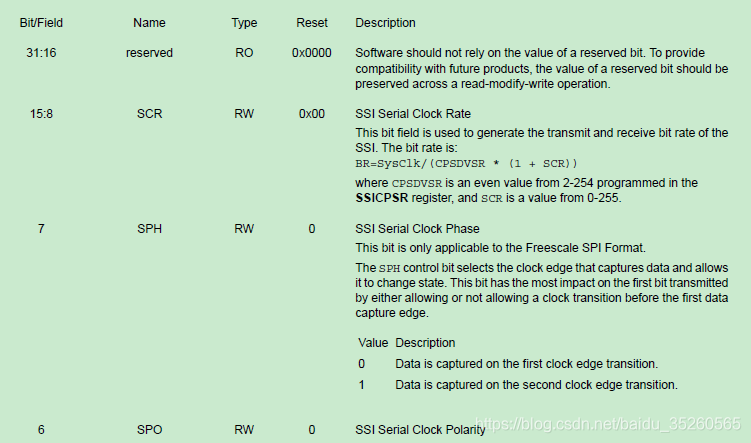
通过tm4c123gh6pz数据手册中SSI_CR0寄存器的示意图及tm4c123gh6pz.h头文件中的宏定义来直观理解一下上面的话。


//*****************************************************************************
//
// The following are defines for the bit fields in the SSI_O_CR0 register.
//
//*****************************************************************************
#define SSI_CR0_SCR_M           0x0000FF00  // SSI Serial Clock Rate
#define SSI_CR0_SPH             0x00000080  // SSI Serial Clock Phase
#define SSI_CR0_SPO             0x00000040  // SSI Serial Clock Polarity
#define SSI_CR0_FRF_M           0x00000030  // SSI Frame Format Select
#define SSI_CR0_FRF_MOTO        0x00000000  // Freescale SPI Frame Format
#define SSI_CR0_FRF_TI          0x00000010  // Synchronous Serial Frame Format
#define SSI_CR0_FRF_NMW         0x00000020  // MICROWIRE Frame Format
#define SSI_CR0_DSS_M           0x0000000F  // SSI Data Size Select
#define SSI_CR0_DSS_4           0x00000003  // 4-bit data
#define SSI_CR0_DSS_5           0x00000004  // 5-bit data
#define SSI_CR0_DSS_6           0x00000005  // 6-bit data
#define SSI_CR0_DSS_7           0x00000006  // 7-bit data
#define SSI_CR0_DSS_8           0x00000007  // 8-bit data
#define SSI_CR0_DSS_9           0x00000008  // 9-bit data
#define SSI_CR0_DSS_10          0x00000009  // 10-bit data
#define SSI_CR0_DSS_11          0x0000000A  // 11-bit data
#define SSI_CR0_DSS_12          0x0000000B  // 12-bit data
#define SSI_CR0_DSS_13          0x0000000C  // 13-bit data
#define SSI_CR0_DSS_14          0x0000000D  // 14-bit data
#define SSI_CR0_DSS_15          0x0000000E  // 15-bit data
#define SSI_CR0_DSS_16          0x0000000F  // 16-bit data
#define SSI_CR0_SCR_S           8

//*****************************************************************************
结命图示及上述代码
SCR是一个多位域, 其中的值为数字 ,起始位为第8位。
所以会有
#define SSI_CR0_SCR_M 定义表明这个多位域
以及对应的:
#define SSI_CR0_SCR_S 8 表明偏移量为8
DSS是一个多位域,有定义:
#define SSI_CR0_DSS_M 0x0000000F // SSI Data Size Select
但其中的值是枚举值,所以紧跟着有一系列定义:
#define SSI_CR0_DSS_4 0x00000003 // 4-bit data
#define SSI_CR0_DSS_5 0x00000004 // 5-bit data
#define SSI_CR0_DSS_6 0x00000005 // 6-bit data
……
SPH是一个单位域,所以有唯一的定义:
#define SSI_CR0_SPH 0x00000080 // SSI Serial Clock Phase
直接访问寄存器的编程例子如下所示:
SSI0_CR0_R = ((5 << SSI_CR0_SCR_S) | SSI_CR0_SPH | SSI_CR0_SPO |
SSI_CR0_FRF_MOTO | SSI_CR0_DSS_8);
SSI0_CR0_R = 0x000005c7;
ulValue = (SSI0_CR0_R & SSI_CR0_SCR_M) >> SSI0_CR0_SCR_S;
//本句代码为从CR0寄存器的SCR位域取出其中的值
2.Software Driver Model
In the software driver model, the API provided by the peripheral driver library is used by applications to control the peripherals.
以下代码为用API配置SSI的CR0寄存器
SSIConfigSetExpClk(SSI0_BASE, 50000000, SSI_FRF_MOTO_MODE_3,
SSI_MODE_MASTER, 1000000, 8);
3.两种方式的优缺及混合使用
api方便易用但代码效率会低,所以适用于对速度要求不严格的配置阶段
直接寄存器方式高效,适用于操作阶段。
For example, the software driver model can be used to configure the peripherals (because this is not performance critical) and the direct register access model can be used for operation of the peripheral (which may be more performance critical). Or, the software driver model can be used for peripherals that are not performance critical (such as a UART used for data logging) and the direct register access model for performance critical peripherals (such as the ADC module used to capture real-time analog data).
来源:CSDN
作者:|静水流深|
链接:https://blog.csdn.net/baidu_35260565/article/details/104476073