一.目的:使用DVE GUI调试现有的Verilog设计。
代码:fifo.v
// ~~~~~~~~~~~~~~~~~~~~~~~~~~~~~~~~~~~~~~~~~~~~~~~~~~~~~~~~~~~~~~~~
// CDANOTE Verilog Synchronous FIFO
// ~~~~~~~~~~~~~~~~~~~~~~~~~~~~~~~~~~~~~~~~~~~~~~~~~~~~~~~~~~~~~~~~

module fifo (clk, rstp, src_in, dst_in, data_in, writep, readp,
	src_out, dst_out, data_out, emptyp, fullp);
input		clk;
input		rstp;
input [7:0]	src_in;
input [7:0]	dst_in;
input [31:0]	data_in;
input		readp;
input		writep;
output [7:0]	src_out;
output [7:0]	dst_out;
output [31:0]	data_out;
output		emptyp;
output		fullp;

// Defines sizes in terms of bits.
//
parameter	DEPTH = 2,
		FULL = (1<<3),	// topmost address in FIFO.
		EMPTY = (1<<3);	// topmost address in FIFO.

reg 		emptyp;
reg		fullp;

// Registered output.
reg [7:0]	src_out;
reg [7:0]	dst_out;
reg [31:0]	data_out;

// Define the FIFO pointers.  A FIFO is essentially a circular queue.
//
reg [(DEPTH-1):0]	tail;
reg [(DEPTH-1):0]	head;

// Define the FIFO counter.  Counts the number of entries in the FIFO which
// is how we figure out things like Empty and Full.
//
reg [DEPTH:0]	count;

// Define our regsiter bank.  This is actually synthesizable!


reg [47:0] fifomem[0:FULL];

// Dout is registered and gets the value that tail points to RIGHT NOW.
//
integer i;
always @(posedge clk or posedge rstp) begin
   if (rstp == 1) begin
      src_out <= 8'b0;
      dst_out <= 8'b0;
      data_out <= 32'b0;
   end
   else begin
      {src_out,dst_out,data_out} <= fifomem[tail];
   end
end

// Update FIFO memory.
always @(posedge clk)
   if (rstp == 1'b0) begin
     if (writep == 1'b1 && fullp == 1'b0)
      fifomem[head] <= {src_in,dst_in,data_in};
   end

// Update the head register.
//
always @(posedge clk) begin
   if (rstp == 1'b1) begin
     head <= 0;
   end
   else begin
      if (writep == 1'b1 && fullp == 1'b0) begin
         // WRITE
         head <= head + 1;
      end
   end
end

// Update the tail register.
//
always @(posedge clk) begin
   if (rstp == 1'b1) begin
      tail <= 0;
   end
   else begin
      if (readp == 1'b1 && emptyp == 1'b0) begin
         // READ
         tail <= tail + 1;
      end
   end
end

// Update the count regsiter.
//
always @(posedge clk) begin
   if (rstp == 1'b1) begin
      count <= 0;
   end
   else begin
      case ({readp, writep})
         2'b00: count <= count;
         2'b01:
            // WRITE
            if (!fullp)
               count <= count + 1;
         2'b10:
            // READ
            if (!emptyp)
               count <= count - 1;
         2'b11:
            // Concurrent read and write.
            count <= count - 1;
      endcase
   end
end


// *** Update the flags
//
// First, update the empty flag.
always @(count) begin
   if (count == EMPTY)
     emptyp = 1'b1;
   else
     emptyp = 1'b0;
end


// Update the full flag
always @(count) begin
   if (count < FULL)
      fullp = 1'b0;
   else
      fullp = 1'b1;
end

endmodule
1.开始
(1)通常的你拿到这个设计,被告知有一个错误,并修复它。
(2)这是用Verilog和Verilog testbench编写的FIFO 测试台通过检查程序检测bug
(3)它打印输出并在出现故障时终止仿真,我们将使用DVE进行调试
(4)FIFO使用count来确定FIFO中有多少项,并确定为空和满。有一个头指针和一个尾指针,分别显示从哪里读写
(5)如果有点晕,需要回到最开始的时候。返回编译并运行步骤。(可以使用清理脚本)
2.FIFO要求
(1)testbench有自己的计数器count checker,用来确定FIFO中有多少输入,以及确定是否为空和满;
(2)如果计数检查器为空,则必须声明空标志;
(3)决不允许下溢
(4)决不允许溢出
3.编译并运行
第一件事是编译并在VCS中运行这个设计。因为要在DVE中进行调试,所以要在您的testbench代码中使用“-debug”标志进行编译,并使用$vcdpluson。
相关代码如下:
% vcs -debug -f run1.f (can use run_debug script)
% simv
打印如下信息:
这就是我们将要调试的错误。
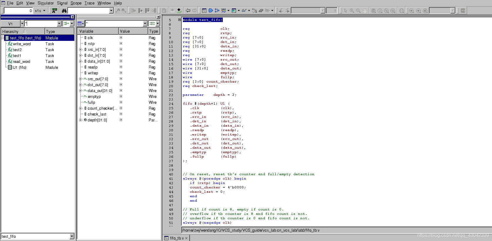
3.1启动DVE并打开vcdplus.vpd仿真结果文件
终端输入下面的命令,打开dve:
dve &
然后,点击File -> Open Database,打开vcdplus.vpd
设计的下拉菜单显示了文件名,V1=vcdplus.vpd,展开test fifo,您可以看到此设计的组件.
3.2在波形窗口中显示测试台信号
从窗口菜单中选择New -> Wave窗口。一个新的wave窗口打开。在“层次结构”窗格中,选择“test_fifo”。注意,它的信号显示在变量窗格中.右键单击test fifo查看层次结构上下文菜单 选择Add to Waves。test_fifo中的所有信号都添加到Wave窗口.如下图:
注意,在主DVE窗口的底部是Console窗格。在控制台窗格中,您将看到一个日志、历史记录和错误/警告选项卡。您在DVE中完成的每个操作都作为Tcl命令记录到此窗格中。您可以在命令提示符中输入Tcl命令。这些选项卡的内容也保存在当前目录的历史日志中
3.3放大在波形窗口
因为我们的错误是在时间250,让我们放大到那里使用底部的时间刻度。在底部的时间标尺上,在大约240点向下点击,拖过250,然后松开。
3.4在错误的地方做个标记
让我们在问题时间做个标记。在波形区域,右键点击从上下文菜单中选择“Create Marker”
3.5在原理图窗口中显示emptyp的连接
在主窗口变量窗格中,选择emptyp。单击工具栏按钮中的显示路径示意图窗口按钮,或从窗口菜单中选择New ->显示路径示意图。在测试台上打开一个带有emptyp连接的路径示意图窗口
3.6在原理图和展开路径中标注pin值
选择Scope ->Annotate Values,现在我们看到emptyp的St0值
3.7显示源代码示意图
3.8编辑源代码以修复错误
Select Scope -> Edit Source
3.9关闭错误仿真结果
4.0DVE中运行模拟
参考文献:
【1】vcs_workshop
来源:CSDN
作者:菜鸟-求指导
链接:https://blog.csdn.net/qq_43042339/article/details/104314931