目录
1 链路聚合配置实验
链路聚合技术可以将多条物理链路聚合为单条逻辑链路,且使得该逻辑链路的带宽是这些物理链路的贷款之和。链路聚合技术主要用于提交互联交换机的逻辑链路的带宽,常常与VLAN、生成树和RSPAN一起作用。
1.1 实验内容
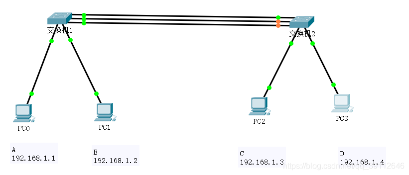
如下图交换机1和交换机2使用三条物理链路相连,这三条物理链路通过链路聚合技术聚合为单条逻辑链路,这条逻辑链路的带宽是三条物理链路的带宽之和。对于交换机1和2,连接着三条物理链路的三个交换机端口聚合为单个逻辑端口。实现MAC帧转发时,逻辑端口的功能等同于物理端口。

1.2 实验原理
连接聚合为逻辑链路的一组物理链路的一组端口称为端口通道。不同的聚合链路对应不同的端口通道,用端口通道号唯一标识每一个端口通道。对于交换机而言,端口通道等同于单个端口,对所有通过端口通道接收到的MAC帧,转发表中创建用于指明该MAC帧源MAC地址与该端口通道之间关联的转发项。
| 交换机 | 端口通道 | 物理端口 |
| 交换机1 | port-channel 1 | FastEthernet0/3 0/4 0/5 |
| 交换机2 | port-channel 2 | FastEthernet0/3 0/4 0/5 |
1.3 关键命令
1.创建并分配端口给端口通道
全局模式
需要将交换机端口FastEthernet 0/3 -0/5分配给编号为1的端口通道,使用以下命令
interface range FastEthernet 0/3-FastEthernet 0/5 //进入一组交换机接口的配置模式
channel-group 1 mode active // 接口模式下使用 1 创建编号为1的端口通道 2 将一组特定的交换机端口(0/3-0/5)分配给端口通道 3 指定active为分配给该端口通道的交换机端口的激活模式。 交换机端口的激活模式与使用的链路聚合控制协议有关。active模式(通过LACP协商过程激活端口,物理链路另一端的模式或是Activite,或是pssive)
2. 指定使用的链路聚合控制协议
接口配置模式
channel-protocol lacp //指定lacp为这一组端口使用的链路聚合控制协议
3 指定MAC帧分发策略
全局模式
port-channel load-balance src-dst-mac //指定根据MAC帧的源和目的MAC地址确定用于传输该MAC帧的物理链路的分发策略
1.4 配置过程
交换机1


交换机2

2 链路聚合与VLAN配置实验
2.1 实验内容
网络拓扑如下图所示,互联交换机的多条物理链路聚合为单条逻辑链路,不同的VLAN内的交换路径共享交换机之间的逻辑链路

2.2 实验原理
分别在三个交换机中创建VLAN 2和VLAN 3 端口映射表和端口通道配置表如下表
交换机1的端口映射表
| VLAN | ACCESS端口 | TRUNK端口 |
| VLAN 2 | 1 | port-channel 1 |
| VLAN 3 | 2 | port-channel 1 |
交换机2的端口映射表
| VLAN | ACCESS端口 | TRUNK端口 |
| VLAN2 | port-channel 1 | |
| VLAN 3 | port-channel 2 |
交换机3的端口映射表
| VLAN | ACCESS端口 | TRUNK端口 |
| VLAN2 | 1 | port-channel 1 |
| VLAN 3 | 2 | port-channel 1 |
端口通道配置表
| 交换机 | 端口通道 | 物理端口 |
| 1 | port-channel 1 | 0/3 0/4 0/5 |
| 2 | port-channel 1 | 0/1 0/2 0/3 |
| port-channel 2 | 0/4 0/5 0/6 | |
| 3 | port-channel 1 | 0/3 0/4 0/5 |
2.3 配置过程
交换机1

交换机 3

交换机 2


3 链路聚合与生成树配置实验
3.1 实验内容
网络结构如下图所示,该网络结构具有以下特点:一是实现交换机之间互联的是由多条物理链路聚合而成的逻辑链路 二是交换机之间存在冗余链路,需要用生成树协议消除交换机之间的环路,网络拓扑如下图所示

3.2 实验原理
分别在四个交换机中创建Vlan2和Vlan3,交换机的端口映射表和端口通道配置表如下表
交换机1
| VLAN | ACCESS口 | TRUNK口 |
| VLAN 2 | 1 | port-channel 1 port-channel 2 |
| VLAN 3 | 2 | port-channel 1 port-channel 2 |
交换机2
| VLAN | ACCESS口 | TRUNK口 |
| VLAN 2 | port-channel 1 port-channel 2 port-channel 3 | |
| VLAN 3 | port-channel 1 port-channel 2 port-channel 3 |
交换机3
| VLAN | ACCESS口 | TRUNK口 |
| VLAN 2 | port-channel 1 port-channel 2 port-chnnel 3 | |
| VLAN 3 | port-channel 1 port-channel 2 port-channel 3 |
交换机4
| VLAN | ACCESS口 | TRUNK口 |
| VLAN 2 | 1 | port-channel 1 port-channel 2 |
| VLAN 3 | 2 | port-channel 1 port-channel 2 |
端口通道配置表
| 交换机 | 端口通道 | 物理端口 |
| 交换机1 | port-channel 1 | 0/3 0/4 0/5 |
| port-channel 2 | 0/5 0/6 0/7 | |
| 交换机2 | port-channel 1 | 0/1 0/2 0/3 |
| port-channel 2 | 0/4 0/5 0/6 | |
| port-channel 3 | 0/7 0/8 0/9 | |
| 交换机3 | port-channel 1 | 0/1 0/2 0/3 |
| port-channel 2 | 0/4 0/5 0/6 | |
| port-channel 3 | 0/7 0/8 0/9 | |
| 交换机4 | port-channel 1 | 0/3 0/4 0/5 |
| port-channel 2 | 0/6 0/7 0/8 |
3.3 配置过程
交换机1/4

交换机 2/3
![]()


![]() +
+
4 链路聚合与RSPAN配置实验
4.1 实验内容
网络拓扑结构如下图所示,交换机2和3之间通过多条物理链路聚合而成的逻辑链路进行链接。嗅探器可以嗅探终端A发送的所有ICMP报文

4.2 实验原理
交换机的端口映射表和端口通道配置表如下表
交换机1的端口映射表
| VLAN | ACCESS口 | TRUNK口 |
| VLAN 2 | 1 | 3 |
| VLAN 3 | 2 | 3 |
| VLAN 5 | 3 |
交换机2的端口映射表
| VLAN | ACCESS口 | TRUNk口 |
| VLAN2 | 1 | 4 |
| VLAN3 | 2 | 4 |
| VLAN4 | 3 | port-channel 1 |
| VLAN5 | 4 port-channel 1 |
交换机3的端口映射表
| VLAN | ACCES口 | TRUN口 |
| VLAN 4 | 1 | port-channel 1 |
| VLAN 5 | port-channel 1 |
端口通道配置表
| 交换机 | 端口通道 | 物理端口 |
| 交换机2 | port-channel 1 | 0/7 0/8 0/9 |
| 交换机3 | port-channel 1 | 0/3 0/4 0/5 |
来源:CSDN
作者:马赛克|
链接:https://blog.csdn.net/qq_39112646/article/details/104001768