01. 开篇:组建小型局域网
实验任务
1、利用一台型号为2960的交换机将2pc机互连组建一个小型局域网;
2、分别设置pc机的ip地址;
3、验证pc机间可以互通。
实验设备
Switch_2960 1台;PC 2台;直连线
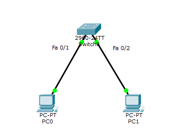
实验设备配置
PC0
IP: 192.168.1.2
Submask: 255.255.255.0
Gateway: 192.168.1.1
PC1
IP: 192.168.1.3
Submask: 255.255.255.0
Gateway: 192.168.1.1
实验验证过程
打开【PC中 >> Desktop >> Commond prompt】
pc0上 ping 192.168.1.3(PC1)的ip地址
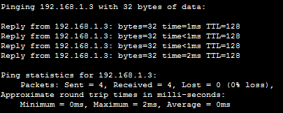
在 PC1上ping 192.168.1.2(PC0)的ip地址

分别在PC0和PC1上ping网关地址192.168.1.1

02. 交换机的基本配置和管理
技术原理
交换机的管理方式基本分为两种:带内管理和带外管理。
通过交换机的Console端口管理交换机属于带外管理;这种管理方式不占用交换机的网络端口,第一次配置交换机必须利用Console端口进行配置。交换机的命令行操作模式主要包括:
用户模式                (EXEC模式) Switch>
特权模式                     Switch#
全局配置模式              Switch(config)
端口模式                 Switch(config-if)#
交换机常用的配置命令行
模式切换指令

enable   进入特权模式(一般简写为en)

config t    进入全局配置模式

interface fa 0/1    进入交换机某个端口视图模式

exit    返回到上级模式

end    从全局以下模式返回到特权模式


快捷指令

帮助信息(如? 、co?、copy?)

命令简写(如 en 的完整命令为 enable)

命令自动补全(Tab)

快捷键(ctrl+c中断测试,ctrl+z退回到特权视图)


reload   重启(在特权模式下)


hostname    X修改交换机名称(在全局配置模式下)


端口配置指令

speed,duplex    配置交换机端口参数

show version    查看交换机版本信息

show running-config   查看当前生效的配置信息

show startup-config    查看保存在NVRAM中的启动配置信息

show interface   查看端口信息

show mac-address-table    查看交换机的MAC地址


选择某个端口Switch(config)# interface  type mod/port

 (type:端口类型,通常有ethernet、Fastethernet、Gigabitethernet;

 mod:端口所在的模块;

 port:在该模块中的编号;):Switch(config)# interface fa 0/1;

 选择多个端口Switch(config)#interface  type mod/startport-endport

如:Switch(config)# interface interface fa 0/1-5  //选择端口 fa 0/1 ~ fa 0/5


 Switch(config-if)#speed [10/100/auto]    设置端口通信速度

 Switch(config-if)#duplex [half/full/auto]    设置端口单双工模式


若交换机设置为auto以外的具体速度,此时应注意保证通信双方也要有相同的设置值。


注意事项:在配置交换机时,要注意交换机端口的单双工模式的匹配,如果链路一端设置的是全双工,另一端是自动协商,则会造成响应差和高出错率,丢包现象会很严重。通常两端设置为相同的模式。


密码设置指令

设置进入特权模式的密码

 Switch(config)# enable password ******


通过console端口连接设备及Telnet远程登录时所需的密码;

  Switch(config)# line console 0   表示配置控制台线路,0是控制台的线路编号。

  Switch(config-line)# login  用于打开登录认证功能。

  Switch(config-line)# password 5ijsj   设置进入控制台访问的密码
实验设备
Switch_2960 1台;PC 1台;配置线;直通线

实验配置设备
PC console端口【PC >> Desktop >>Terminal】
修改交换机名、端口
Switch>enable    //进入特权模式
Switch#conf  t   //进入配置模式
Switch(config)#hostname  S2960    //修改交换机名
S2960(config)#interface fa 0/1    //选择端口
S2960(config-if)#speed 100       //修改端口配置
S2960(config-if)#duplex full
S2960(config-if)#exit
同时将PC的网卡改成全双工模式,100M速率,否则链路不通
查看交换机各项配置参数
Switch#show version
Switch#show run
Switch#show interface
Switch#show mac-address-table
Switch#config t
修改交换机特权
Switch(config)#enable  password cisco  //激活特权模式密码为cisco
Switch(config)#no enable password      //取消特权模式密码
修改交换机连接和telnet密码
Switch(config)#line console 0        //选择控制台线路
Switch(config-line)#password cisco   //激活该控制台线路密码为cisco
Switch(config-line)#login          //打开登录认证功能
Switch(config-line)#no password    //取消密码
03. 交换机的Telnet远程登陆配置
技术原理
实验步骤
Switch(config)# int vlan 1
Switch(config-if)# ip address **IP** **submask***
3、配置用户登录密码
Switch(config)# enable password ******* //设置进入特权模式的密码
Switch(config)# line vty 0 4        //
Switch(config-line)# password abc
Switch(config-line)# login
实验设备
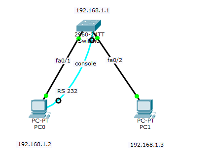
实验设备配置
Swicth0设置(通过PC0的terminal设置 )
Switch>en         //进入特权模式
Switch#conf  t   //进入全局配置模式
Switch(config)#interface vlan 1     //创建并进入VLAN 1的接口视图(默认交换机的所有端口都在VLAN1中)
Switch(config-if)#ip address 192.168.1.1 255.255.255.0    //在VLAN 1 接口上配置交换机远程管理的IP地址
Switch(config-if)#no shutdown   //开启接口
Switch(config-if)#exit

Switch(config)#line vty 0 4         //进入远程登录用户管理视图,0-4个用户
Switch(config-line)#login           //打开登录认证功能
Switch(config-line)#password cisco  //配置远程登录的密码为5ijsj,密码明码显示
Switch(config-line)#privilege level 1  //配置远程登录用户的权限为最低权限1(最高权限3)
Switch(config-line)#end

Switch#show run   //显示当前交换机配置情况
实验验证
PC0 桌面选项卡中的CMD,命令提示符
ping 192.168.1.1   //成功以后,再做下一步
telnet 192.168.1.1
   输入password:cisco    //登录成功,进入用户模式
Switch>Enable//进入特权模式
Switch#
PC1 桌面选项卡中的CMD,命令提示符
ping 192.168.1.1   //成功以后,再做下一步
telnet 192.168.1.1
   输入password:cisco    //登录成功,进入用户模式
Switch>Enable//进入特权模式
Switch#
04. 交换机的端口聚合配置
技术原理
interface range interface_name1 to interface_name2
Switchport mode trunk
channel-group 1 mode on 加入链路组1并开启
Switch#show etherchannel summary:显示相关汇聚端口组的信息;
参数:
    interface_name1:聚合起始端口;
    interface_name2:聚合结束端口;
    trunk:表示端口可以转发所有Vlan包,trunk mode 的接口可以同时传输多个VLAN信息的;
    trunk mode 常用在两个SWITCH and ROUTER ,SWITCH and SWITCH 之间;
    channel-group: 将2个或多个物理端口组合在一起成为一条逻辑的链路 ,同时也形成了一个逻辑端口port-channel
    switchport mode access:直接接主机,所属VLAN中的接口,都是access
实验设备
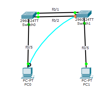
实验设备配置
Switch>enable
Switch#config  t
Switch(config)#interface range fa 0/1-2         //同时选择端口fa0/1 fa0/2
Switch(config-if-range)#Switchport mode trunk   //设置端口模式为trunk
Switch(config-if-range)#channel-group 1 mode on   //加入链路组1并开启
Switch(config-if-range)#exit
Switch(config)#port-channel load-balance dst-ip  //按照目标主机IP地址数据分发来实现负载平衡
Switch(config)#exit

Switch#show etherchannel summary    //显示以太信道概况

Switch1
Switch>en
Switch#config  t
Switch(config)#interface range f0/1-2
Switch(config-if-range)#Switchport mode trunk   //设置端口模式为trunk
Switch(config-if-range)#channel-group 1 mode on   //加入链路组1并开启
Switch(config-if-range)#exit
Switch(config)#port-channel load-balance dst-ip  //按照目标主机IP地址数据分发来实现以太网通道组负载平衡
Switch(config)#exit

Switch#show etherchannel summary  //显示以太网通道组的情况
实验验证
PC0 ping PC1        Reply
PC1 ping PC0        Reply
05. 交换机划分Vlan配置
技术原理
1) VLAN是指在一个物理网段内。进行逻辑的划分,划分成若干个虚拟局域网,VLAN做大的特性是不受物理位置的限制,可以进行灵活的划分。VLAN具备了一个物理网段所具备的特性。相同VLAN内的主机可以相互直接通信,不同VLAN间的主机之间互相访问必须经路由设备进行转发,广播数据包只可以在本VLAN内进行广播,不能传输到其他VLAN中。
2)Port VLAN是实现VLAN的方式之一,它利用交换机的端口进行VALN的划分,一个端口只能属于一个VLAN。
3)Tag VLAN是基于交换机端口的另一种类型,主要用于是交换机的相同Vlan内的主机之间可以直接访问,同时对不同Vlan的主机进行隔离。Tag VLAN遵循IEEE802.1Q协议的标准,在使用配置了Tag VLAN的端口进行数据传输时,需要在数据帧内添加4个字节的8021.Q标签信息,用于标示该数据帧属于哪个VLAN,便于对端交换机接收到数据帧后进行准确的过滤。
实验说明
在同一个局域网中,要实现PC0、PC2为同一个分组,PC1、PC3属于同一个分组,PC0、PC1,PC2、PC3使用分别使用同一个交换机;
在4个PC使用同一个网关的情况下,将4个PC进行Vlan分组划分,实现两个分组之间的相互隔离;
实验步骤
1. 新建Packet Tracer拓扑图;
2. 划分VLAN;
3. 将端口划分到相应VLAN中;
4. 设置Tag VLAN Trunk属性;
5. 测试
实验设备
Switch_2960 2台;PC 4台;直连线
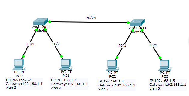
实验设备配置
IP: 192.168.1.2
Submark: 255.255.255.0
Gateway: 192.168.1.1
PC1
IP: 192.168.1.3
Submark: 255.255.255.0
Gateway: 192.168.1.1
PC2
IP: 192.168.1.4
Submark: 255.255.255.0
Gateway: 192.168.1.1
PC3
IP: 192.168.1.5
Submark: 255.255.255.0
Gateway: 192.168.1.1
Switch0
Switch>en
Switch#conf t
Switch(config)#vlan 2    //向交换机添加新的虚拟端口 vlan 2
Switch(config-vlan)#exit
Switch(config)#vlan 3    //添加新的vlan 3
Switch(config-vlan)#exit

Switch(config)#interface fa 0/1   //切换到fa 0/1端口,并将该端口绑定到vlan2
Switch(config-if)#switch access vlan 2
Switch(config-if)#exit

Switch(config)#interface fa 0/2      //切换到fa 0/2端口,并将该端口绑定到vlan3
Switch(config-if)#switch access vlan 3
Switch(config-if)#exit

Switch(config)#inter fa 0/24      //切换到fa 0/24(示例中为交换机连接端口),
Switch(config-if)#switchport mode trunk  //并将更改其连接模式为trunk
Switch(config-if)#end

Switch#show vlan      //显示交换机的 vlan 配置情况
Switch1
Switch>en
Switch#conf t
Switch(config)#vlan 2
Switch(config-vlan)#exit
Switch(config)#vlan 3
Switch(config-vlan)#exit

Switch(config)#interface fa 0/1
Switch(config-if)#switchport access vlan 2
Switch(config-if)#exit
Switch(config)#inter fa 0/2
Switch(config-if)#switchport access vlan 3
Switch(config-if)#exit

Switch(config)#inter fa 0/24
Switch(config-if)#switch mode trunk
Switch(config-if)#end

Switch#show vlan
实验验证
PC1 ping PC2 timeout
PC1 ping PC3 Reply
来源:https://www.cnblogs.com/benjamin77/p/8979195.html